Explore the history, definition, and significance of Unified Modeling Language (UML) in software development. Learn why UML is essential for specifying, visualizing, and documenting software systems. Discover what UML is not and its role in standardizing methodologies.
Please find below an Image/Link to download the presentation.
The content on the website is provided AS IS for your information and personal use only. It may not be sold, licensed, or shared on other websites without obtaining consent from the author. If you encounter any issues during the download, it is possible that the publisher has removed the file from their server.
You are allowed to download the files provided on this website for personal or commercial use, subject to the condition that they are used lawfully. All files are the property of their respective owners.
The content on the website is provided AS IS for your information and personal use only. It may not be sold, licensed, or shared on other websites without obtaining consent from the author.
E N D
Presentation Transcript
UML Unified Modeling Language Balla Tibor NLV8 Technologies Ltd. ballatibi@gmail.com
References 1. Jeszenszky P ter - Programoz s technol gi k, UML diasor, 2018 : https://arato.inf.unideb.hu/jeszenszky.peter/download/prt/presentations /uml.pdf 2. Harald St rrle: UML 2, 2007, Budapest, Panem 3. Introduction To OMG's Unified Modeling Language http://www.omg.org/UML/what-is-uml.htm 4. OMG Unified Modeling Language (OMG UML) Version 2.5.1. December 2017. http://www.omg.org/spec/2.5.1/ 5. Szoftverfejleszt s - Az UML s fontosabb diagramjai (prezent ci ) - https://slideplayer.hu/slide/2069589/ 6. Szoftverfejleszt s - Ficsor Lajos, Krizs n Zolt n, Mileff P ter, https://www.tankonyvtar.hu/hu/tartalom/tamop425/0046_szoftverfejles ztes/adatok.html 7. https://www.uml-diagrams.org
The definition of UML- The OMG's Unified Modeling Language (UML) helps you specify, visualize, and document models of software systems, including their structure and design [...]. (You can use UML for business modeling and modeling of other non-software systems too.)
What isnt UML? - Not a programming language Not a software development methodology Not a general process model Not a television series Not food Not Unconditional Maximum Likelihood (a statistical method) Not ...
Short history of UML- In the 1970s the first structured software development methodologies arrive In the 1980s the first object oriented methods Even small differences in methods sparked large debates among experts (War of Methodologies) The methodologies needed common ground Three Amigos Grandy Booch Jim Rumbaugh (OMT) Ivar Jacobson (OOSE) In an effort to standardize these methods, OMG (Object Management Group) releases UML 0.9 in 1995. Current version: 2.5.1, released in december 2017
The significance of UML- It s not a silver bullet UML is not intended as an invention that will stand for eternity, but a temporary solution for a slowly developing field. Effects: Consolidates knowledge standardization Emphasis is placed on modelling
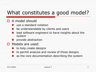
What is a model? - A model is a representation of something that can be used to make (cheaper, easier, faster) predictions about the original. Business/technical processes analysis and design Existing system documentation Describes the system from a given perspective Modelling can be a part of all phases of the software development cycle It has significant emphasis in the early phases
The importance of modeling- Mistakes most often occur at the requirement engineering or designing stages. The later they are discovered, the more expensive they become. The time spent on creating a valid, correct model is always worth it.
What is a metamodel? - A metamodel is the model of a model. The metamodel of UML is a model that completely models itself. A metamodel enables the creation of new models Meta Object Facility MOF is an open, platform independant metadata management framework, which enables the development of model- and metadata-driven systems.
The structure of UML- Layered design, the core of UML is very dense, simple and highly descriptive Every system is an instance of a model Every model is an instance of a metamodel Every metamodel is an instance of a meta-metamodel
UML diagrams - There are two main groups of diagrams: Structural diagrams: describe static behaviour, states Behaviour diagrams: describe dynamic behaviour, cooperation, activity, state changes. The dynamic behaviour of a system can be described as a series of changes over time. The two groups of diagrams can overlap.
UML diagrams - Behaviour diagrams: state machine diagram use case diagram activity diagram interaction diagram: interaction overview diagram sequence diagram timing diagram communication diagram
Generic graphic elements- Comment Dog-eared rectangle Constraint Dog-eared rectangle, that uses an arbitrary language or OCL.
Generic graphic elements- Package Used for grouping model elements Stereotype Defines an extension of one or more metaclasses, enables the use of platform- or domain-specific terminology or notation to supplement the extended metaclass. Given above or before the name of a model element. Notation: << >>
Class diagrams - Describes the model s classes and interactions between them. Static Three type: Analysis class diagram: Represent the structure of the domain Design class diagram: The future details of the implementation are present Implementation class diagram: Equivalent to the class notion of the implementing language
Class notations - Class Abstract class Class that can t be instantiated Active Class Class that can be active by itself (not just in response to something else) Interface
Activity diagram- Models processes, business processes Represents the inner logic of a system Shows What are the elementary steps of a complex business process What can be done in parallel Are there alternate paths in the process graph Activity diagrams have a lot in common with flowcharts
Activity diagram- Action Accept Signal Action Send Signal Action Conditional Node Loop Node
Activity diagram- Contol Flow Fork Node Join Node Decision Node Merge Node Flow Final Initial State Final State
Use case diagram - Identifies actors interacting with the system Identifies the classes interacting in a system, and their relationships: Gives a picture of how the users will use the system Can be used to define the borders of a system The users are always outside the system Very important tool of requirement engineering
State machine diagram - Shows the possible states and state changes of an object during its life cycle. Concerns abstract states By OO definitions, the state of an object is given by the values of its attributes specific state During modeling, some sets of specific states are equivalent.
State machine diagram - These are called abstract states. For example, if we re talking about a student completing a class, there are two abstract states: Successful: got a final mark greater than 1 (this abstract state is the set of four specific states) Unsuccessful: doesn t have signature, or has a signature but no final mark, or has a final mark of 1 (three specific states) These two abstract states are enough to decide if a student can take the next course