The ZDD Data Structure for Signal Timing Analysis
Explore the ZDD data structure, where each channel produces positive waveforms split into fragments for calorimetric analysis. Learn about timing analysis relative to the buffer start and maximizing hit probability in ZDD for BEPCII beam crossings. Discover the correction of event timing and more for precise measurements.

Download Presentation

Please find below an Image/Link to download the presentation.
The content on the website is provided AS IS for your information and personal use only. It may not be sold, licensed, or shared on other websites without obtaining consent from the author. If you encounter any issues during the download, it is possible that the publisher has removed the file from their server.
You are allowed to download the files provided on this website for personal or commercial use, subject to the condition that they are used lawfully. All files are the property of their respective owners.
The content on the website is provided AS IS for your information and personal use only. It may not be sold, licensed, or shared on other websites without obtaining consent from the author.
E N D
Presentation Transcript
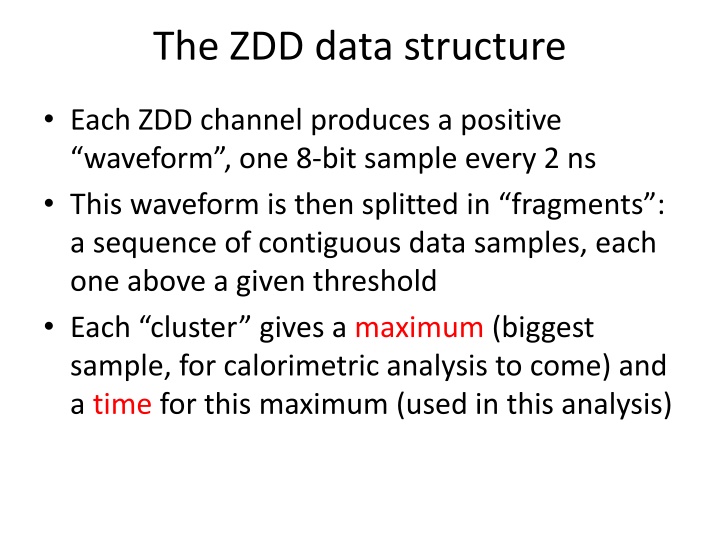
The ZDD data structure Each ZDD channel produces a positive waveform , one 8-bit sample every 2 ns This waveform is then splitted in fragments : a sequence of contiguous data samples, each one above a given threshold Each cluster gives a maximum (biggest sample, for calorimetric analysis to come) and a time for this maximum (used in this analysis)
The ZDD data structure This time is relative to the start of the ZDD data buffer, so (indirectly) to L1*, that closes the buffer Only the first part of the buffer, 1600 ns, is analyzed. The second part is thrown away. L1*-8200ns L1*
Finding the ZDD signal timing The ZDD is sensitive to most of the BEPCII beam crossings. There is much background! We must maximize the probability of a hit in the ZDD In addition to the radiative Bhabha selection we require: A strong missing photon: Emiss>0.4 GeV A low emission angle: |cos( )| > 0.98
ZDD bottom half ZDD top half The red histogram shows ZDD fragment times (16 ns/bin) when the missing photon points to the ZDD side (cos( ) > 0.98) The black histogram shows ZDD fragment times when the missing photon points to the other side (cos( ) <- 0.98) There is a clear accumulation around +200 ns in both plots, FWHM 40-50 ns wide
ZDD bottom half ZDD top half The same plot, zoomed (2ns/bin) on the interesting region.
ZDD bottom half ZDD top half Here we correct the timing by subtracting the BESIII Event start time , the time scale is again 2ns/bin The event-to-event variation of the L1* latency is removed Both peaks are much narrower, and the time shift is because the L1* trigger cable enters the ZDD bottom FADC first The widths (not gaussian, 16ns) are due to the FADCs trigger sensing granularity
Countercheck 1 The same plot, for the bad control sample 0.8 < |cos( )| < 0.97
Countercheck 2 The same plot, for a bad FADC time window, starting at -7200ns before L1*
Conclusions We have demonstrated that accumulations of ZDD hits correlate strongly with 2 BESIII subsystems: The MDC because the accumulation depends on the polar angle of the missing photon The TOF because the timing is made more precise by using the event t0 Also, we have shown that if we shift the trigger window, the correlation vanishes
Outlook for the 2014-2015 run The ZDD start of the time window appears correct The time window will be shortened to 400 ns from 1600 much more tolerable for DAQ The ZDD signal will become part of the BESIII DQM, and will be monitored by ZDD people to make sure that it does not move