Thermal Analysis of Rotor-Pad Friction System
Explore the thermal behavior of a rotor-pad friction system under varying pressure scenarios. Analyze pad stationary initial velocity, backing plate rigidity, and prescribed boundary conditions affecting rotational speed. Discover solutions for mechanical and thermal control in this study of pad pressure and rotor contact.

Download Presentation

Please find below an Image/Link to download the presentation.
The content on the website is provided AS IS for your information and personal use only. It may not be sold, licensed, or shared on other websites without obtaining consent from the author. If you encounter any issues during the download, it is possible that the publisher has removed the file from their server.
You are allowed to download the files provided on this website for personal or commercial use, subject to the condition that they are used lawfully. All files are the property of their respective owners.
The content on the website is provided AS IS for your information and personal use only. It may not be sold, licensed, or shared on other websites without obtaining consent from the author.
E N D
Presentation Transcript
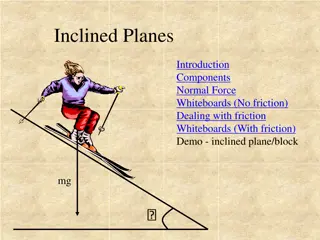
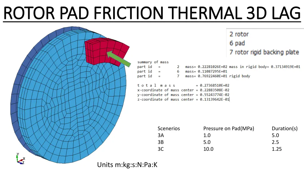
ROTOR PAD FRICTION THERMAL 3D LAG ROTOR PAD FRICTION THERMAL 3D LAG Scenerios 3A 3B 3C Pressure on Pad(MPa) 1.0 5.0 10.0 Duration(s) 5.0 2.5 1.25 Units m:kg:s:N:Pa:K
3A 3B 3C
Pad stationary INITIAL VELOCITY @t=0s
Backing Plate 1. Rigid 2. Fixed z direction 3. Rotation about center z axis Pressure applied to Pad to slow down rotation 1. 1MPa : 7kN : 5.0 sec 2. 5MPa : 35kN : 2.5 sec 3. 10MPa : 70kN : 1.25 sec Rotor fixed to Backing Plate
(rigid) PID 7 PID 6 PID 2 GEOMETRY
NB. Rotational speed(rad/s) versus time(sec) Max 50 rad/s - Min 0 rad/s PRESCRIDED BOUNDARY CONDITIONS Velocity versus time
SCALE FACTOR 1. 1MPa 2. 5MPa 3. 10MPa NB. Pressure applied to pad PAD PRESSURE
KEYWORD CONTROL (Mechanical and Thermal Solution)
PAD PAD SURFACE AREA 7.0e-03 m^2 PRESSURE 1MPa : Force =7kN 5MPa : Force = 35kN 10MPa : Force = 70kN ROTOR CONTACT ROTOR & PAD
PARTS & MATERIAL DATA
3A 3B 3C
Temp(K) 300 320 Rise Time(s) 3a 0.8 2.6 3b 0.3 0.75 3c 0.175 0.5 Rotor EID Rotor EID Pad EID Temp(K) 340 400 500 580 Rise Time(s) 3a 0.8 1.6 3.25 4.5 Pad EID 3b 0.25 0.75 0.65 1.5 3c 0.15 0.3 0.4 0.9


")
 versus time(sec)")


")