Three-Phase AC Systems and Voltage Relationships
Explore the basics of three-phase AC systems, phase voltages, and line voltages, along with the relationships between them. Learn about the phase-star connection, voltage amplitudes, and phase displacements in this informative content.

Download Presentation

Please find below an Image/Link to download the presentation.
The content on the website is provided AS IS for your information and personal use only. It may not be sold, licensed, or shared on other websites without obtaining consent from the author. If you encounter any issues during the download, it is possible that the publisher has removed the file from their server.
You are allowed to download the files provided on this website for personal or commercial use, subject to the condition that they are used lawfully. All files are the property of their respective owners.
The content on the website is provided AS IS for your information and personal use only. It may not be sold, licensed, or shared on other websites without obtaining consent from the author.
E N D
Presentation Transcript
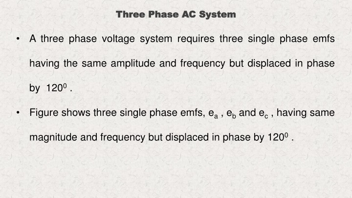
Three Phase AC Three Phase AC System System A three phase voltage system requires three single phase emfs having the same amplitude and frequency but displaced in phase by 1200. Figure shows three single phase emfs, ea, eband ec, having same magnitude and frequency but displaced in phase by 1200.
Three Phase AC Three Phase AC System System
Basics of AC Circuit UNIT-IV
Relation Relation Between Between Phase STAR CONNECTION STAR CONNECTION Phase Voltage Voltage and and Line Line Voltage Voltage VRN, VYN, VBNare called the phase voltages VRY, VYB, VBR are called the line voltages
Relation Relation Between Between Phase STAR CONNECTION STAR CONNECTION Phase Voltage Voltage and and Line Line Voltage Voltage From the figure: VRY= VRN- VYN VYB= VYN- VBN VBR= VBN- VRN
Relation Relation Between Between Phase STAR CONNECTION STAR CONNECTION Phase Voltage Voltage and and Line Line Voltage Voltage VRN= VmSin t VYN=VmSin ( t +120) VBN= VmSin ( t - 120) From the figure: VRY= VRN- VYN VYB= VYN- VBN VBR= VBN- VRN
Relation Relation Between Between Phase STAR CONNECTION STAR CONNECTION Phase Voltage Voltage and and Line Line Voltage Voltage From the figure: V VRY VYB= VYN- VBN VBR= VBN- VRN RY= V = VRN RN- - V VYN YN
Relation Relation Between Between Phase STAR CONNECTION STAR CONNECTION Phase Voltage Voltage and and Line Line Voltage Voltage From the figure: V VRY V VYB VBR= VBN- VRN RY= V YB= V = VRN = VYN RN- - V VYN YN- - V VBN YN BN
Relation Relation Between Between Phase STAR CONNECTION STAR CONNECTION Phase Voltage Voltage and and Line Line Voltage Voltage From the figure: V VRY V VYB V VBR RY= V YB= V BR= V = VRN = VYN = VBN RN- - V VYN YN- - V VBN BN- - V VRN YN BN RN
Relation Relation Between Between Phase STAR CONNECTION STAR CONNECTION Phase Voltage Voltage and and Line Line Voltage Voltage
Relation Relation Between Between Phase STAR CONNECTION STAR CONNECTION Phase Voltage Voltage and and Line Line Voltage Voltage For Balanced System VRN =VYN =VBN= VP phase voltages VRY= VYB =VBR=VL line voltages
Relation Relation Between Between Phase STAR CONNECTION STAR CONNECTION Phase Voltage Voltage and and Line Line Voltage Voltage 2+ ??? 2+ 2????????? 60 2+ 2??????? 60 ???= ??? 2+ ?? = ?? 21 2+ ?? 2+ 2?? = ?? 2 ???= 3?? ??= ???
Relation Relation Between Between Phase STAR CONNECTION STAR CONNECTION Phase Current Current and and Line Line Current Current I1, I2, I3, are called the phase currents IR, IY, IBare called the line Currents
Relation Relation Between Between Phase STAR CONNECTION STAR CONNECTION Phase Current Current and and Line Line Current Current For Balanced System I1=I2= I3= IP phase currents IR= IY =IB= IL line Currents From the star circuit IL= IP
Relation Relation Between Between Phase DELTA CONNECTION DELTA CONNECTION Phase Voltage Voltage and and Line Line Voltage Voltage V12, V23, V31 are called the phase voltages VRY, VYB, VBR are called the line voltages
Relation Relation Between Between Phase DELTA CONNECTION DELTA CONNECTION Phase Voltage Voltage and and Line Line Voltage Voltage For Balanced System V12=V23=V31 =VP phase voltages VRY= VYB =VBR=VL line voltages
Relation Relation Between Between Phase DELTA CONNECTION DELTA CONNECTION Phase Voltage Voltage and and Line Line Voltage Voltage From the circuit V12=VRY V23= VYB V31 =VBR So VL = VP
Relation Relation Between Between Phase DELTA CONNECTION DELTA CONNECTION Phase Current Current and and Line Line Current Current I1, I2, I3are called the phase currents IR, IY,IB are called the line currents
Relation Between Phase Current and Line Current Relation Between Phase Current and Line Current DELTA CONNECTION DELTA CONNECTION From the figure: IR= I2- I1 IB= I1- I3 IY= I3- I2 Let I1= ImSin t I2= ImSin ( t +120) I3= ImSin ( t - 120)
Relation Between Phase Current and Line Current Relation Between Phase Current and Line Current DELTA CONNECTION DELTA CONNECTION From the figure: IR= I2- I1 IB= I1- I3 IY= I3- I2 Let I1= ImSin t I2= ImSin ( t +120) I3= ImSin ( t - 120)
Relation Between Phase Current and Line Current Relation Between Phase Current and Line Current DELTA CONNECTION DELTA CONNECTION From the figure: I IR R= I IB= I1- I3 IY= I3- I2 = I2 2- - I I1 1
Relation Between Phase Current and Line Current Relation Between Phase Current and Line Current DELTA CONNECTION DELTA CONNECTION From the figure: I IR R= I I IB B= I IY= I3- I2 = I2 2- - I I1 1 = I1 1- - I I3 3
Relation Between Phase Current and Line Current Relation Between Phase Current and Line Current DELTA CONNECTION DELTA CONNECTION From the figure: I IR R= I I IB B= I I IY Y= I = I2 2- - I I1 1 = I1 1- - I I3 3 = I3 3- - I I2 2
Relation Between Phase Current and Line Current Relation Between Phase Current and Line Current DELTA CONNECTION DELTA CONNECTION For Balanced System IR= IB= IY= IL I1=I2= I3= IP
Relation Between Phase Current and Line Current Relation Between Phase Current and Line Current DELTA CONNECTION DELTA CONNECTION 2+ ?2 2+ ?? 2+ 2?1?2??? 60 2+ 2??????? 60 ??= = ?? ?1 21 2+ ?? 2+ 2?? = ?? 2 ??= 3?? ??= ???
THREE PHASE POWER MEASUREMENT THREE PHASE POWER MEASUREMENT The total active power in a three phase circuit, will be the summation of the active powers of all the three phases. The power in a three phase circuit can be measured with the help of wattmeters. There are three methods to measure power in a three phase AC circuit. The three methods are, 1. Three wattmeter method of measurement of power 2. Two wattmeter method of measurement of poweR 3. One wattmeter method of measurement of power
THREE PHASE POWER MEASUREMENT THREE PHASE POWER MEASUREMENT Three wattmeter method of measurement of power
THREE PHASE POWER MEASUREMENT THREE PHASE POWER MEASUREMENT Three wattmeter method of measurement of power Consider a three phase four wire star connected system as shown in Fig. To measure the total power of the circuit, connected across three phases as shown in the Fig. The current coils of the three wattmeter`s are connect in series across each phase of the circuit, and the potential across the phase and the neutral (N) three wattmeter`s are coil is connected
THREE PHASE POWER MEASUREMENT THREE PHASE POWER MEASUREMENT Three wattmeter method of measurement of power The wattmeter reading of W1will be the product of current flowing through the current coil (IR), voltage drop across the potential coil (VRN) and the cos of angle between IRand VRN. The phasor diagram of the system is shown in the fig.
THREE PHASE POWER MEASUREMENT THREE PHASE POWER MEASUREMENT Three wattmeter method of measurement of power
THREE PHASE POWER MEASUREMENT THREE PHASE POWER MEASUREMENT Three wattmeter method of measurement of power
THREE PHASE POWER MEASUREMENT THREE PHASE POWER MEASUREMENT Three wattmeter method of measurement of power
THREE PHASE POWER MEASUREMENT THREE PHASE POWER MEASUREMENT Two wattmeter method of measurement of power
THREE PHASE POWER MEASUREMENT THREE PHASE POWER MEASUREMENT Two wattmeter method of measurement of power
THREE PHASE POWER MEASUREMENT THREE PHASE POWER MEASUREMENT Two wattmeter method of measurement of power
THREE PHASE POWER MEASUREMENT THREE PHASE POWER MEASUREMENT Two wattmeter method of measurement of power
THREE PHASE POWER MEASUREMENT THREE PHASE POWER MEASUREMENT One wattmeter method of measurement of power
PROBLEMS PROBLEMS 1. Two wattmeters are connected to measure the input power to a balanced 3-phase load by the two-wattmeter method. If the instrument readings are 8kW and 4kW, determine (a) the total power input and (b) the load power factor.
PROBLEMS PROBLEMS 2. indicate the total power input to be 12kW. The power factor is 0.6. Determine the readings of each wattmeter. Two wattmeters connected to a 3-phase motor
PROBLEMS PROBLEMS 3. connected in star to a 415 V, 3-phase supply. Determine Three loads, each of resistance 30 ohm are (a) the system phase voltage, (b) the phase current and (c) the line current.
PROBLEMS PROBLEMS 4. Three identical coils, each of resistance 10ohm and inductance 42mH are connected (a) in star and (b) in delta to a 415V, 50 Hz, 3-phase supply. Determine the total power dissipated in each case.
PROBLEMS PROBLEMS