Time Frame Contents and Expected Data Volumes by Jeff Landgraf
Coordinate systems and data structures are crucial for handling expected data volumes. An overview of DAQ computing and data formats is provided, including a case study on ASIC data format. The organization of DAQ files is illustrated with an example detailing the structure of time frames. Explore the essential information required for managing data volumes, background noise, and configurations in data acquisition.

Download Presentation

Please find below an Image/Link to download the presentation.
The content on the website is provided AS IS for your information and personal use only. It may not be sold, licensed, or shared on other websites without obtaining consent from the author.If you encounter any issues during the download, it is possible that the publisher has removed the file from their server.
You are allowed to download the files provided on this website for personal or commercial use, subject to the condition that they are used lawfully. All files are the property of their respective owners.
The content on the website is provided AS IS for your information and personal use only. It may not be sold, licensed, or shared on other websites without obtaining consent from the author.
E N D
Presentation Transcript
Time Frame Contents and Expected Data Volumes Jeff Landgraf o Time Frame Data Structure o Time Frame information contents o Conversion of simulation information to DAQ use o Time structure o Data Volumes, Background and Noise
Coordinate Systems A minimum of 3 coordinate systems are going to be needed: Detector System: Implemented in dd4hep as 64 bit, user specified bit field e.g. BarrelHCal: epic-23.12.0 <id>system:8,sector:5,tower:6,tile:3</id> epic-nightly: <id>system:8,eta:5,phi:9</id> DAQ: Combine and/or generalize. DAM, RDO, FEB, ASIC, Channel Global: Detector, x, y, z 3/21/2024 Joint SRO/Electronics and DAQ WG 2
DAQ Computing: Data Format Case Study (H2GCROC3A) This is the data format of a prototype ASIC not the final ASIC, my points are conceptual! (N. Nowitski) Potential interesting data: Full ASIC data (despite containing up to 17 channels of data without hits) {RAW} Channels without hits removed, but containing n samples for channels hit {CHANNEL} Channels with samples suppressed and only TOA/TOT information {TOATOT} Processed TOA/TOT information improved using sample information, but without saving samples {ENHANCED} Data volume information Granularity of readout is 1/4 chip (18 channels). Data is 3x10 bit words per sample, but the meaning of the three words depends on the Tc, Tp flags Data is NOT pedestal subtracted, rather the pedestals are shifted via calibration to the same value Can configure fixed # time samples read out Can configure to disable certain Tc/Tp Combinations Suppress Banks in some timeframes: /TF#/NHCAL/DAM01/RAW /TF#/NHCAL/DAM01/CHANNEL /TF#/NHCAL/DAM01/TOATOT /TF#/NHCAL/DAM01/ENHANCED (1 in 1000) (1 in 10) (1 in 10) (always) Implications for data formats & readers Generic named data navigation Detailed bank reader plugins 3 3/21/2024 Joint SRO/Electronics and DAQ WG
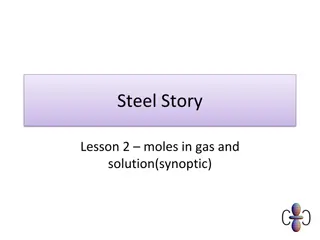
DAQ File Organization (Example) TF_Head: BX#1: ASIC_1 ASIC_2 ( ) ASIC_N BX#2: ASIC_1 ASIC_2 ASIC_3 ( ) SC: ASIC_1 ( ) BX#3 ASIC_1 ASIC_2 ( ) ( ) TF_Tail Time Frame #1 Detector #1 DAM #1 RDO #1 RAW Time Frame #2 Detector #2 RDO #2 ( ) Processed #1 Time Frame #3 Detector #3 DAM #N RDO #3 ( ) Processed Info #1 Time Frame #3 ( ) ( ) Processed #N Time Frame #4 Detector #N RDO #N ( ) Processed Info #1 Processed Info #N Time Frame #5 Slow Controls Beam Info (GTU) Time Frame #6 ( ) Format by necessity complex, extendable & variable Processed Info #N Time Frame #7 Scalers 3/21/2024 Joint SRO/Electronics and DAQ WG 4
DAQ File Organization (Example) TF_Head: BX#1: ASIC_1 ASIC_2 ( ) ASIC_N BX#2: ASIC_1 ASIC_2 ASIC_3 ( ) SC: ASIC_1 ( ) BX#3 ASIC_1 ASIC_2 ( ) ( ) TF_Tail Time Frame #1 Detector #1 DAM #1 RDO #1 RAW Time Frame #2 Detector #2 RDO #2 ( ) Processed #1 Time Frame #3 Detector #3 DAM #N RDO #3 ( ) Processed Info #1 Time Frame #3 ( ) ( ) Processed #N Time Frame #4 Detector #N RDO #N ( ) Processed Info #1 Processed Info #N Time Frame #5 Slow Controls Beam Info (GTU) Time Frame #6 ( ) Format by necessity complex, extendable & variable Processed Info #N Time Frame #7 Scalers 3/21/2024 Joint SRO/Electronics and DAQ WG 5
Readers Two distinct sets of readers needed Data Bank Navigation rdr = getBank( NameOfBank ) or rdr = getBank(TimeFrame, lfhcal/dam_3/rdo_6/raw ) Detector Bank specific readers (presumably implemented as plugins) hit = rdr->nextHit() hit.bx hit.highResTOA hit.channel hit.adc Could, of course have multiple readers instantiated at a time for simultaneous decoding One likely needs to fill intermediate data structure for processing, so time frame for DAQ and time frame for tracking need not be tied together! 3/21/2024 Joint SRO/Electronics and DAQ WG 6
Time Frame Data I used simulations from Zhengqiao Zhang & Jakub Ceska Type Energies File Nominal Rate Used Rate Hits/Event DIS 18x275 GeV /gpfs/mnt/gpfs02/eic/zhangzq/EPIC/NewReco/analysis_DIS/all.tree.edm4eic.root 83 kHz 500 kHz (10x275 GeV) 485 Proton Beam Gas 275 GeV /gpfs/mnt/gpfs02/eic/zhangzq/EPIC/NewReco/analysis_ProtonGas/all_protonGas.eicr econ.tree.edm4eic.root 32.6 kHz (10000Ahr) 350.3 kHz (100Ahr) 420 Electron Beam Gas 10 GeV (highest beam current) /gpfs/mnt/gpfs02/eic/ceska/readout/podio_merged.root 3.177MHz (10000Ahr) 34.1 MHz (100 Ahr) 15.5 Hit Mapping. Heuristics are used for mapping hits Channel: Not used for ITS3/Astropix ASIC: reticule for ITS3 Sensor for Astropix FEB for non-asic dets ASIC for asic based dets Heuristic function for each detector: Map RecHits (x,y,z,cellID) (channel, ASIC, RDO) Software is in: Files with the detailed results: wiki -> Talks and Slide Library -> DAQ Directory Link -> Data Volumes -> 240312-Simulated DataRates.txt RDO: RDOs are associated with nearby ASICS. In final system most, but not all, detectors the FEB->RDO map can be set to minimize data rate variation. Avg rates matter here https://github.com/jml985/epicJTools 3/21/2024 Joint SRO/Electronics and DAQ WG 7
Coordinate Systems In DD4HEP (23.12.0) Detector Coordinates Implementation SiBarrelVertex System,Layer,Module,Sensor,x,y System indicates layer, layer not used, module implemented, Grid represents pixels SiBarrelTracker System,Layer,Module,Sensor,x,y Single system, Layer implemented, 128 modules in each layer (unphysical?), Grid represents pixels SiBarrelEndcap System,Layer,Module,Sensor,x,y System+layer represents disk, 36 modules each in spokes, Grid represents pixels Fwd/Back MPGDEndcap System,Layer,Module,Sensor,x,y 2 Layers represent disks, 48 modules represent spokes, grid represents detector resolution, not channels MPGDBarrel System,Layer,Module,Sensor,x,y 128 modules represent staves, grid represents detector resolution not channels OuterMPGDBarrel System,Layer,Module,Sensor,x,y Even modules Electron Side, Odd modules Hadron Side, grid represents detector resolution not channels LFHCAL System,ModX,ModY,TowX,TowY,rlayerz,layerz All implemented, layerz are summed over HCalEndcapPInsert System,Layer,Slice,x,y 65 layers, grouped into 13 for 8k channels (not grouped?) hex grid x,y values alternate even/odd only EcalEndcapP/Insert System,barrel,module,layer,slize,fiberx,fibery,x,y Only grid used, but grid represents channels. Insert is not distinct detector, but x,y grid is shifted HcalEndcapN System,barrel,module,layer,slice,x,y No combination of layer/grid resuls in 3256 channels! EcalEndcapN System,sector,module,x,y No grid values set, but module count seems to represent channels HCalBarrel System,Sector,Tower,Tile Fully implemented. 7680 Towers ECalBarrelSiFi System,Sector,Row,Towers Implemented, but z positions are set, Also all hits need to are doubled because dual readout on east/west ECalBarrelImaging System,Sector,Layer,Slice,Grid,Fiber,z No sensible values, TOFBarrel System,Layer,Module,Sensor Modules are staves, Counts represent old channel counts TOFEndcap System,Layer,Module,idx,idy Idxy even for inner layer, odd for outer layer, Counts represent old channel counts dRICH hpDIRC pfRICH 3/21/2024 Joint SRO/Electronics and DAQ WG 8
Coordinate MAP to DAQ for Data Volume Tests Detector Coordinates Implementation SiBarrelVertex System,Layer,Module,Sensor,xx,yy Distribute evenly in Z for each layer (asics/rdo 108/4, 144/5, 359/12) SiBarrelTracker System,Layer,Module,Sensor,xx,yy Distribute evenly in Z for each layer (asics/rdo 1578/50, 2294/72) SiBarrelEndcap System,Layer,Module,Sensor,xx,yy Distribute evenly in R for each disk (asics/rdo 313/10, 949/30, 977/31, 976/31, 972/31, 313/10, 949/30, 977/31, 969/31, 957/31) Fwd/Back MPGDEndcap System,Layer,Module,Sensor,xx,yy Distribute evenly in R for each disk (asics/rdo 128/8) MPGDBarrel System,Layer,Module,Sensor,xx,yy Distribute evenly in Z (asic/rdo 512/32) OuterMPGDBarrel System,Layer,Module,Sensor,xx,yy Distribute evenly in Z for each panel (asics/rdo 1084/69) LFHCAL System,ModX,ModY,TowX,TowY,rlayerz,layerz Each module gets 1 asic (8 towersx7channels), RDO covers 8x4 grid of modules HCalEndcapPInsert System,Layer,Slice,xx,yy Distribute 154/7 asic over x,y grid x 7 layers. Distribute 10 RDO over positional grid EcalEndcapP/Insert System,barrel,module,layer,slize,fiberx,fibery,xx,yy Distribute channels over grid using 25x25 mm pitch, asics define by 8x4 grid, rdo defined by 32x16 grid HcalEndcapN System,barrel,module,layer,slice,xx,yy Distribute 64 asic in R, 2 RDO in R EcalEndcapN System,sector,module,xx,yy Distribute 125 asic in R, 8 RDO in R HCalBarrel System,Sector,Tower,Tile 1 asic per tile, 4 asic per sector ECalBarrelSiFi Systen,Sector,Row,Towers 1 asic per sector, 24 sector per rdo. Each asic/rdo doubled for hadron/electron side sensors ECalBarrelImaging System,Sector,Layer,Slice,Grid,Fiber,zz Distribute evenly in grid by layer (asic/rdo -> 14537/52, 15827/57, 16429/59, 17719/63) TOFBarrel System,Layer,Module,Sensor Distribute evenly in Z (asic/rdo 18432/288) TOFEndcap System,Layer,Module,idx,idy Distribute evenly in R for each layer (asic/rdo 1816/106) dRICH hpDIRC pfRICH 3/21/2024 Joint SRO/Electronics and DAQ WG 9
Hit Sizes & Noise rates Detector Bits / hit (readout) Bits / hit (tape) Bits / Noise Hit (tape) Noise Hit Rate Estimates (hz/channel) Reduction Notes MAPS 2x64 2x64 2x64 1e-3 (~6.25 ) 64 bits per pixel, but hits likely to show up in adjoining 2usec frames MPGD 5x64 1x64 0 30 (~4.5 ) Charge sharing, cluster finding for reduction Most Calorimeter (Caloroc) 18x6x64 64 0 1000 (~3.7 ) 18 channel segmentation in caloroc, 6 time samples, feature finding for reduction, additional/noise reduction possible via cluster finding Fwd/Back eCal 6x64 64 0 1000 (~3.7 ) 6 time sample estimate (possible onboard feature finding, but not yet assumed). Feature finding for reduction (additional/noise reduction possible via cluster finding) Astropix 64 64 ? ? Forward TOF 9x64 64 0 30 (~4.5 ) 3x3 asic segmentation & cluster finding dRICH 64 64 64/200 3000-300,000 (~2 ) Software triggering Default 64 64 ? ? 3/21/2024 Joint SRO/Electronics and DAQ WG 10
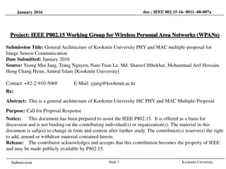
Event Timing (measured wrt actual collision T0) Expectation DIS t(v=c) vs z t (ns) Z (mm) 3/21/2024 Joint SRO/Electronics and DAQ WG 11
Event Timing Expectation DIS Electron Beam t(v=c) vs z t (ns) Z (mm) 3/21/2024 Joint SRO/Electronics and DAQ WG 12
Event Timing Expectation DIS Electron Beam Proton Beam t(v=c) vs z t (ns) Z (mm) 3/21/2024 Joint SRO/Electronics and DAQ WG 13
Event Timing Electron Beam Gas Simulation (RecHits) DIS Proton Beam Gas 3/21/2024 Joint SRO/Electronics and DAQ WG 14
Event Timing Electron Beam Gas Simulation (RecHits) DIS Proton Beam Gas 3/21/2024 Joint SRO/Electronics and DAQ WG 15
Event Timing Electron Beam Gas Simulation (RecHits) DIS Proton Beam Gas 3/21/2024 Joint SRO/Electronics and DAQ WG 16
Event Timing in the Simulations 1. DIS, Proton Beam Gas, Electron Beam Gas (eventual Synchrotron radiation) should be randomly distributed according to desired beam energies & intensities 2. The source of the extended times should be understood (if they are not already understood). If real, a simulated events hits should be distributed in time according to Thit = nominal event T0 + Thit_sim. For all detectors. 3. The hits for the MAP detectors need 2 special characteristics 1. The time should be set to the beginning of the 2us period it occurs within. 2. The hit should be replicated in either the prior or following 2us period depending on whether it is closer to the end of the hit period or closer to the beginning. 4. I would add noise only to the MAPS and dRICH. Assume that reasonable cluster finding in other detectors will suppress nearly all of the noise. 3/21/2024 Joint SRO/Electronics and DAQ WG 17
Results What was processed No RICH detectors (no RecHits) No Far Backward: simulations don t cover the driving physics, but have numbers from other methods No Far Forward: I didn t finish coordinate maps (B0 at least should be done) MPGD/TOF should provide channel map, but was initially confused and didn t correct 3/21/2024 Joint SRO/Electronics and DAQ WG 18
Hit Rates DIS + Proton Beam + Electron Beam (No noise added) 3/21/2024 Joint SRO/Electronics and DAQ WG 19
Data rate to RDOs DIS + Proton Beam + Electron Beam (No noise added) 3/21/2024 Joint SRO/Electronics and DAQ WG 20
Data Rate to Tape DIS + Proton Beam + Electron Beam (No noise added) 3/21/2024 Joint SRO/Electronics and DAQ WG 21
Channel Rates Full Detector, channel rates Counts Hit Rate (Hz) 3/21/2024 Joint SRO/Electronics and DAQ WG 22
Channel Rates Similar to previous rates, but missing detectors, so somewhat higher Channel rates, All detectors Counts Hit Rate (Hz) 3/21/2024 Joint SRO/Electronics and DAQ WG 23
Channel Rates Surprising !?! Channel rates, All detectors Perhaps not, only 2880 channels covering full length of ECAL Counts Hit Rate (Hz) 3/21/2024 Joint SRO/Electronics and DAQ WG 24
EcalEndcapN vs EcalBarrelScFi Must Double check, but likely -> Need to adjust FEB/RDO count -> Need to have real discussions regarding noise 3/21/2024 Joint SRO/Electronics and DAQ WG 25
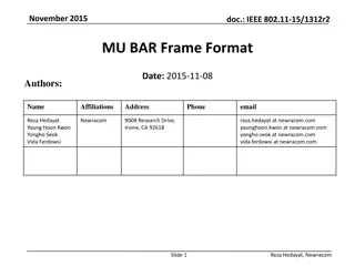
Rate Summaries Detector Max Channel Rate Max ASIC Rate Avg RDO Throughput Beam Related Data To Tape (Gbps) Noise Target (Gbps) Threshold target (Sigma) SiBarrelVertex 359 kHz 441 Mbps 9.3 Gbps 3 Gbps >6.5 SiBarrelTracker 3.5 kHz 9.1 Mbps 1.1 Gbps 300 Mbps >6.5 SiBarrelEndcap 1.1 MHz 87.4 Mbps 23.3 Gbps 8 Gbps >6.5 ForwardMPGDEndcap 3.0 MHz 476 Mbps 1.5 Gbps ASIC limit Noise sensitivity is in ASIC readout speed & quality of BackwardMPGDEndcap 5.0 MHz 644 Mbps 2.1 Gbps ASIC limit data reduction via feature MPGDBarrel 21.5 kHz 92.6 Mbps 592 Mbps ASIC limit OuterMPGDBarrel 5.1 kHz 13.1 Mbps 360 Mbps ASIC limit LFHCAL 35.3 kHz 801 kHz 2.4 Gbps (needs balance) 1.9 Gbps ASIC/RDO limit HCalEndcapPInsert 101 kHz 2.1 Mhz 27.7 Gbps (needs more!) 4.1 Gbps ASIC/RDO limit finding EcalEndcapP/Insert 241 kHz 5.8 Mhz 1.4 Gbps (needs balance) 11.8 Gbps ASIC/RDO limit HcalEndcapN 408 kHz 5.2 Mhz 43.7 Gbps (needs more!) 809.3 Mbps ASIC/RDO limit EcalEndcapN 735 kHz 12.6 MHz 5.8 Gbps (needs balance) 7.7 Gbps ASIC/RDO limit HCalBarrel 2.2 kHz 15.6 kHz 1.9 Gbps 139 Mbps ASIC/RDO limit ECalBarrelSiFi 302.9 kHz 836 kHz 112 Gbps (Needs More!) 8.3 Gbps ASIC/RDO limit ECalBarrelImaging 4.4 kHz 10.7 Mbps 2.7 Gbps TOFBarrel 2.1 kHz 3.9 Mbps 1.1 Gbps ASIC limit TOFEndcap 25 kHz 21.9 Mbps 516 Mbps ASIC limit dRICH < 300 kHz hpDIRC pfRICH SUM 77.3 Gbps 3/21/2024 Joint SRO/Electronics and DAQ WG 26
Final Thoughts At the last background meeting there was a presentation from Andrii Natochii. The synchrotron radiation, in the current beamline configuration floods the detectors with about 1e6 x the DIS and beam gas backgrounds. Current status is waiting to see to what extent this can be reduced. The overall summary of the new simulations is that (Excluding Synchrotron Radiation) the data volumes are moderately higher than earlier expectations. I expect the full rate to top out around 150Gbps, assuming the synchrotron radiation can be brought under control. There are several results that do impact our assumptions for RDO counts, and possibly expectations for ASIC/FEE performance. Lots of details to check! There are several next steps Incorporate RICHs Move to RawHits rather than RecHits Add Far Backward / Far Forward detectors Evaluate the noise requirements Check that the ASIC rates capabilities are consistent with the highest rate sections of the detector Re-evaluate the RDO distributions for the detectors with high rates 3/21/2024 Joint SRO/Electronics and DAQ WG 27


")
")
")


")


")