Transformer Tests for Efficiency and Equivalent Circuit Determination
Learn how transformer losses can be experimentally determined using short-circuit and open-circuit tests. These tests provide essential data for evaluating transformer efficiency and calculating its equivalent circuit parameters.
Download Presentation

Please find below an Image/Link to download the presentation.
The content on the website is provided AS IS for your information and personal use only. It may not be sold, licensed, or shared on other websites without obtaining consent from the author. If you encounter any issues during the download, it is possible that the publisher has removed the file from their server.
You are allowed to download the files provided on this website for personal or commercial use, subject to the condition that they are used lawfully. All files are the property of their respective owners.
The content on the website is provided AS IS for your information and personal use only. It may not be sold, licensed, or shared on other websites without obtaining consent from the author.
E N D
Presentation Transcript
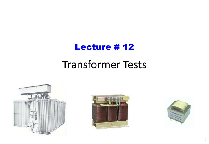
Lecture # 12 Transformer Tests 1
Transformer Tests Losses may be determined experimentally using the short- circuit test and the open-circuit test. (These tests are used mainly with power transformers.) They provide the data needed to determine a transformer s equivalent circuit and to compute its efficiency. 2
Transformer Tests The Short-Circuit Test: The Figure below shows the test setup for the short-circuit test. In the SCT, the secondary terminals of the transformer are short circuited, and the primary terminals are connected to a fairly low- voltage source. The input voltage is adjusted until the current in the short circuited windings is equal to its ratedvalue. The input voltage, current, and power aremeasured. Short circuit test 3
Transformer Tests The Short-Circuit Test: Since the input voltage is so low during the SCT, negligible current flows through the excitationbranch. If the excitation current is ignored, then all the voltage drop in the transformer can be attributed to the series elements in the circuit. The magnitude of the series impedances referred to the primary side of the transformer is: =Vsc I Zeq sc Short circuit test 4
Transformer Tests The Short-Circuit Test: The power factor of the current is given by Psc PF = cos( )= (lagging) V sc Isc The current angle is thus negative, and the overall impedance angle is positive: V sc I sc 0 Zeq sc sc I I Psc =cos 1 =Vsc =Vsc The series impedance Zeq is equalto: = Req + jXeq Zeq Short circuit test 26
Transformer Tests The Short-Circuit Test: Example: Measurements on the high side of a 240/120-volt, 4.8-kVA transformer yield Vsc = 11.5 V and Psc = 172 W at the rated current. DetermineZeq. Solution: Since ZL= 0, the only impedance in the circuit isZeq. 4.8 103 = 20A 240 = Isc =Vsc I =11.5= 0.575 20 Psc V sc I sc =0.575 41.6 Zeq sc =cos 1 =41.6 =Vsc I = 0.43+ j0.382 Zeq sc Zeq 27
Transformer Tests The Open-Circuit Test: The setup for the open-circuit test is shown in the Figure below. In the OCT, a transformer's secondary winding is open circuited, and its primary winding is connected to a full-rated linevoltage. All the input current must be flowing through the excitation branch of the transformer. The series elements Rp and Xp are too small in comparison to RC and XM to cause a significant voltage drop. Thus, all the inputvoltage is dropped across the excitationbranch. 28 Open circuittest
Transformer Tests The Open-Circuit Test: The input voltage, input current, and input power to the transformer are measured. 1 =IOC j1 whereY = Y E E V R X OC C M POC PF = cos( )= (lagging) VOCIOC POC VOCIOC =cos 1 Y =IOC E V OC Open circuittest 29
Transformer Tests The Open-Circuit Test: The setup for the open-circuit test is shown in the Figure below. Apply the full rated voltage. Since the load current is zero, only exciting current results. Since the exciting current is small, power loss in the winding resistance is negligible, and the power that you measure is just core loss. 30 Open circuittest
Transformer Tests The Open-Circuit Test: Example: An open-circuit test on the transformer of the previous Example yields a core loss of 106 W. Determine the transformer s efficiency when supplying the full, rated VA to a load at unity power factor. Solution: Since the transformer is supplying the rated VA, its current is the full, rated current. From the short-circuit test, the copper loss at full rated current is 172 W.Thus, copper loss = 172 W core loss = 106 W (Measured above) output = 4800 W (Rated) input = output + losses = 5078 W Thus, = Pout/Pin = (4800/5078 ) 100 = 94.5% 10
Transformer Tests Example: A single phase, 100 MVA, 200/80 kV transformer has the following test data: open circuit: IOC = 20 A, VOC = 200 kV with POC = 10 kW losses short circuit: VSC = 30 kV, with PSC = 500 kWlosses Determine the model parameters. a=2.5 11
Transformer Tests Solution: From the short-circuittest From the open-circuittest =IOC 100 106 200 103 S = 0.1 10 3 Y S I sc = Irated = = = 500A E V V OC V OC IOC IOC Y =V 1 POC =VSC ISC =30 kV= 60 500A =cos 1 =89.86 Z eq 1 P = 0.1 10 3 89.86 S =cos sc =88.1 E V sc I sc =60 88.1 OC =Vsc I Y = 0.244 j100 S Zeq E sc 1 = 4.1Meg RC =0.244 10 6 Zeq = 2 + j60 Req= 2 and Xeq= 60 1 = =10k and X M 100 10 6 33
