Transmission Impairments and Attenuation in Communication Systems
Learn about the transmission impairments like attenuation in communication systems, the effects on signal quality, and how engineers address these challenges with amplifiers and repeaters. Explore the concept of decibels for measuring signal strength loss or gain due to attenuation. Delve into the important considerations for ensuring reliable signal transmission.

Download Presentation

Please find below an Image/Link to download the presentation.
The content on the website is provided AS IS for your information and personal use only. It may not be sold, licensed, or shared on other websites without obtaining consent from the author. If you encounter any issues during the download, it is possible that the publisher has removed the file from their server.
You are allowed to download the files provided on this website for personal or commercial use, subject to the condition that they are used lawfully. All files are the property of their respective owners.
The content on the website is provided AS IS for your information and personal use only. It may not be sold, licensed, or shared on other websites without obtaining consent from the author.
E N D
Presentation Transcript
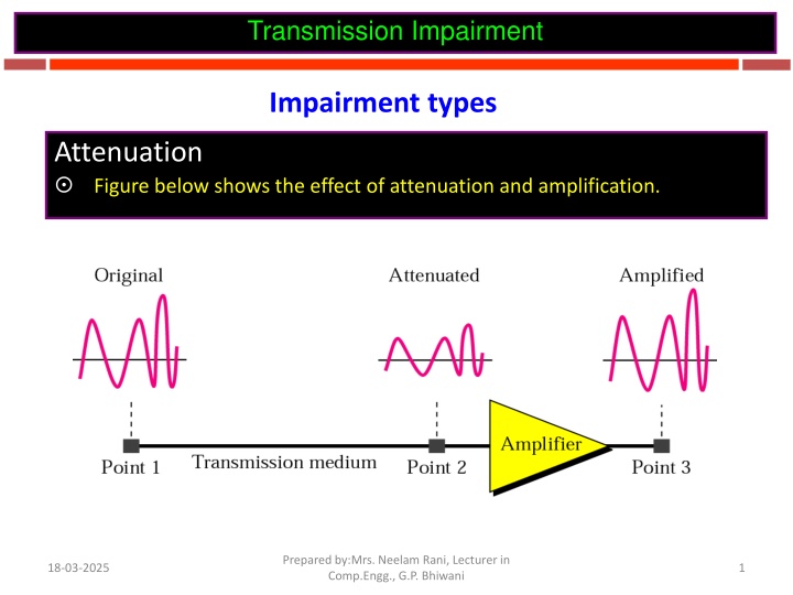
Transmission Impairment Impairment types Attenuation Figure below shows the effect of attenuation and amplification. Prepared by:Mrs. Neelam Rani, Lecturer in Comp.Engg., G.P. Bhiwani 18-03-2025 1
Part 3: Transmission Impairments With any communications system, the signal that is received may differ from the signal that is transmitted, due to various transmission impairments. Consequences: For analog signals: degradation of signal quality For digital signals: bit errors The most significant impairments include Attenuation and attenuation distortion Delay distortion Noise Prepared by:Mrs. Neelam Rani, Lecturer in Comp.Engg., G.P. Bhiwani 18-03-2025 2
Attenuation Attenuation: signal strength falls off with distance. Depends on medium For guided media, the attenuation is generally exponential and thus is typically expressed as a constant number of decibels per unit distance. For unguided media, attenuation is a more complex function of distance and the makeup of the atmosphere. Three considerations for the transmission engineer: 1. A received signal must have sufficient strength so that the electronic circuitry in the receiver can detect the signal. 2. The signal must maintain a level sufficiently higher than noise to be received without error. These two problems are dealt with by the use of amplifiers or repeaters. Prepared by:Mrs. Neelam Rani, Lecturer in Comp.Engg., G.P. Bhiwani 18-03-2025 3
Transmission Impairment Attenuation Decibel To show that a signal has lost or gained strength, we use the unit of the decibel. The decibel (dB) measures the relative strengths of two signals or one signal at two different points. Note that the decibel is: Negative if a signal is attenuated and Positive if a signal is amplified. 18-03-2025 PI and P2 are the powers of a signal at points 1 and 2, respectively. Prepared by:Mrs. Neelam Rani, Lecturer in Comp.Engg., G.P. Bhiwani 4
Transmission Impairment Attenuation Decibel Note that some books define the decibel in terms of voltage instead of power. In this case, because power is proportional to the square of the voltage, the formula is: dB = 20 log 10 (V2 / V1) Prepared by:Mrs. Neelam Rani, Lecturer in Comp.Engg., G.P. Bhiwani 18-03-2025 5
Transmission Impairment Attenuation Decibel Note that some books define the decibel in terms of voltage instead of power. In this case, because power is proportional to the square of the voltage, the formula is: dB = 20 log 10 (V2 / V1) Prepared by:Mrs. Neelam Rani, Lecturer in Comp.Engg., G.P. Bhiwani 18-03-2025 6
Transmission Impairment Attenuation Example Suppose a signal travels through a transmission medium and its power is reduced to one-half. This means that P2 = P1. In this case, the attenuation (loss of power) can be calculated as: dB = 10 log10 (P2 / P1) = 10 log10 (1/2 P1 / P1) = 10 log10 (0.5)) = 10 (-0.3) dB = -3 Other Numerical Examples from book Prepared by:Mrs. Neelam Rani, Lecturer in Comp.Engg., G.P. Bhiwani 18-03-2025 7
Attenuation Distortion (Following the previous slide) 3. Attenuation is often an increasing function of frequency. This leads to attenuation distortion: some frequency components are attenuated more than other frequency components. Attenuation distortion is particularly noticeable for analog signals: the attenuation varies as a function of frequency, therefore the received signal is distorted, reducing intelligibility. Prepared by:Mrs. Neelam Rani, Lecturer in Comp.Engg., G.P. Bhiwani 18-03-2025 8
Delay Distortion Delay distortion occurs because the velocity of propagation of a signal through a guided medium varies with frequency. Various frequency components of a signal will arrive at the receiver at different times, resulting in phase shifts between the different frequencies. Delay distortion is particularly critical for digital data Some of the signal components of one bit position will spill over into other bit positions, causing intersymbol interference, which is a major limitation to maximum bit rate over a transmission channel. Prepared by:Mrs. Neelam Rani, Lecturer in Comp.Engg., G.P. Bhiwani 18-03-2025 9
Transmission Impairment Distortion Distortion means that the signal changes its form or shape. Distortion can occur in a composite signal made of different frequencies. Each signal component has its own propagation speed through a medium and, therefore, its own delay in arriving at the final destination. Differences in delay may create a difference in phase if the delay is not exactly the same as the period duration. In other words, signal components at the receiver have phases different from what they had at the sender. The shape of the composite signal is therefore not the same. Due to propagation speeds Prepared by:Mrs. Neelam Rani, Lecturer in Comp.Engg., G.P. Bhiwani 18-03-2025 10
Transmission Impairment Distortion Figure below shows the effect of distortion on a composite signal. Prepared by:Mrs. Neelam Rani, Lecturer in Comp.Engg., G.P. Bhiwani 18-03-2025 11
Noise (1) For any data transmission event, the received signal will consist of the transmitted signal, modified by the various distortions imposed by the transmission system, plus additional unwanted signals that are inserted somewhere between transmission and reception. The undesired signals are referred to as noise, which is the major limiting factor in communications system performance. Four categories of noise: Thermal noise Intermodulation noise Crosstalk Impulse noise Prepared by:Mrs. Neelam Rani, Lecturer in Comp.Engg., G.P. Bhiwani 18-03-2025 12
Noise (2) Thermal noise (or white noise) Due to thermal agitation of electrons It is present in all electronic devices and transmission media, and is a function of temperature. Cannot be eliminated, and therefore places an upper bound on communications system performance. Intermodulation noise When signals at different frequencies share the same transmission medium, the result may be intermodulation noise. Signals at a frequency that is the sum or difference of original frequencies or multiples of those frequencies will be produced. E.g., the mixing of signals at f1 and f2 might produce energy at frequency f1 + f2. This derived signal could interfere with an intended signal at the frequency f1 + f2. Prepared by:Mrs. Neelam Rani, Lecturer in Comp.Engg., G.P. Bhiwani 18-03-2025 13
Noise (3) Crosstalk It is an unwanted coupling between signal paths. It can occur by electrical coupling between nearby twisted pairs. Typically, crosstalk is of the same order of magnitude as, or less than, thermal noise. Impulse noise Impulse noise is non-continuous, consisting of irregular pulses or noise spikes of short duration and of relatively high amplitude. It is generated from a variety of cause, e.g., external electromagnetic disturbances such as lightning. It is generally only a minor annoyance for analog data. But it is the primary source of error in digital data communication. Prepared by:Mrs. Neelam Rani, Lecturer in Comp.Engg., G.P. Bhiwani 18-03-2025 14
Transmission Impairment Noise Noise is another cause of impairment. Several types of noise, such as thermal noise, induced noise, cross-talk, and impulse noise, may corrupt the signal. Thermal noise is the random motion of electrons in a wire which creates an extra signal not originally sent by the transmitter. Induced noise comes from sources such as motors and appliances. These devices act as a sending antenna, and the transmission medium acts as the receiving antenna. Cross-talk is the effect of one wire on the other. One wire acts as a sending antenna and the other as the receiving antenna. Impulse noise is a spike (a signal with high energy in a very short time) that comes from power lines, lightning, and so on. Prepared by:Mrs. Neelam Rani, Lecturer in Comp.Engg., G.P. Bhiwani 18-03-2025 15
Transmission Impairment Noise Figure shows the effect of noise on a signal. Prepared by:Mrs. Neelam Rani, Lecturer in Comp.Engg., G.P. Bhiwani 18-03-2025 16
Transmission Impairment Noise Signal-to-Noise Ratio (SNR) To find the theoretical bit rate limit, we need to know the ratio of the signal power to the noise power. The signal-to-noise ratio is defined as: SNR = average signal power / average noise power We need to consider the average signal power and the average noise power because these may change with time. Prepared by:Mrs. Neelam Rani, Lecturer in Comp.Engg., G.P. Bhiwani 18-03-2025 17
Transmission Impairment Noise Figure shows the idea of SNR Prepared by:Mrs. Neelam Rani, Lecturer in Comp.Engg., G.P. Bhiwani 18-03-2025 18
Transmission Impairment Noise Signal-to-Noise Ratio (SNR) SNR is actually the ratio of what is wanted (signal) to what is not wanted (noise). A high SNR means the signal is less corrupted by noise; A low SNR means the signal is more corrupted by noise. Because SNR is the ratio of two powers, it is often described in decibel units, SNRdB, defined as: SNRdB= 10 log10 SNR Prepared by:Mrs. Neelam Rani, Lecturer in Comp.Engg., G.P. Bhiwani 18-03-2025 19
Transmission Impairment Noise Signal-to-Noise Ratio (SNR) Example Prepared by:Mrs. Neelam Rani, Lecturer in Comp.Engg., G.P. Bhiwani 18-03-2025 20


")
")
")