Troubleshooting Guide for SIMPLIS Simulation Software in Power Electronics Component Design
Learn when and how to use the SIMPLIS Debug Report for troubleshooting power electronics component designs. Discover how to create and interpret the report to identify simulation issues and optimize performance. Debugging tips and parameters are also covered in this comprehensive guide.

Download Presentation

Please find below an Image/Link to download the presentation.
The content on the website is provided AS IS for your information and personal use only. It may not be sold, licensed, or shared on other websites without obtaining consent from the author. If you encounter any issues during the download, it is possible that the publisher has removed the file from their server.
You are allowed to download the files provided on this website for personal or commercial use, subject to the condition that they are used lawfully. All files are the property of their respective owners.
The content on the website is provided AS IS for your information and personal use only. It may not be sold, licensed, or shared on other websites without obtaining consent from the author.
E N D
Presentation Transcript
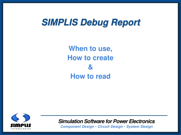
SIMPLIS Debug Report When to use, How to create & How to read Simulation Software for Power Electronics Component Design Circuit Design System Design 1
If everything is going well, you dont need this report However, if your simulation gets stuck, bogged down, errors out before normal completion or runs far slower than it should 2
The SIMPLIS Debug Report generator requires that simulation debug information has been explicitly requested for a previous simulation. To turn ON Debug Info Put the following statement into the F11 window of the top-level SIMPLIS schematic: .options max_debug_data_size=10 Run the simulation Then, choose Simulator | Debug Simulation 3
The size of the SIMPLIS .dbg file can be set to be as large as you want (until you run out of hard disk space) The larger the .dbg file, the larger the file size of the Debug Report, and the longer it will take to generate In general, only request debug information for schematics that are misbehaving, remove the .OPTION statement when done 4
*** DEBUG PARSER PARAMETERS: *** *** *** *** *** numevents:20 minuqpct :50 minwin :1n mintc :-50 maxtcjump:5 5
*** DEBUG PARSER PARAMETERS: *** numevents:20 *** minuqpct :50 % *** minwin :1n *** mintc :-50 *** maxtcjump:5 The Debug Report looks for 3 types of problems: 1) Chattering: True if Number of Unique events minuqpct % * numevents && Time interval for numevents events to occur minwin (s) 2) The smallest Time Constant during any event TC mintc 3) A jump in value of TC maxtcjump while TC mintc 6
T: 5.0245280684906833e-005; DELTA: 7.809421623893072e-007; TC: -21; S: 2 !R$R2(2), 4 !R$R3(2); ***NEW TOPOLOGY *** SV: 0 V(C1), 2 I(V1), 1 V(V1) T: 5.0374696344769413e-005; DELTA: 1.294156598625795e-007; TC: -64; S: 2 !R$R2(3), 4 !R$R3(3); ***NEW TOPOLOGY *** SV: 0 V(C1), 2 I(V1), 1 V(V1) T: 5.0245280684906833e-005; DELTA: 7.809421623893072e-007; T: 5.0374696344769413e-005; DELTA: 1.294156598625795e-007; Delta Time (in seconds) between current and previous event Time (in seconds) of each event 7
T: 5.0245280684906833e-005; DELTA: 7.809421623893072e-007; TC: -21; S: 2 !R$R2(2), 4 !R$R3(2); ***NEW TOPOLOGY *** SV: 0 V(C1), 2 I(V1), 1 V(V1) T: 5.0374696344769413e-005; DELTA: 1.294156598625795e-007; TC: -64; S: 2 !R$R2(3), 4 !R$R3(3); ***NEW TOPOLOGY *** SV: 0 V(C1), 2 I(V1), 1 V(V1) TC: -21; S: 2 !R$R2(2), 4 !R$R3(2); TC: -64; S: 2 !R$R2(3), 4 !R$R3(3); PWL RefDes(state) Index of PWL RefDes Smallest Time Constant (TC) in current PWL Topology -- TC in log(base 2) All PWL elements that changed state to create this current topology 8
ID ID Q Diode NMOS 2 3 4 3 Capacitor 3 2 vD vDS 1 1 V 1 2 Vout Simple Switch 1 - OFF 2 - ON Comparator t 1 Simulation Software for Power Electronics Component Design Circuit Design System Design
T: 5.0245280684906833e-005; DELTA: 7.809421623893072e-007; TC: -21; S: 2 !R$R2(2), 4 !R$R3(2); ***NEW TOPOLOGY *** SV: 0 V(C1), 2 I(V1), 1 V(V1) T: 5.0374696344769413e-005; DELTA: 1.294156598625795e-007; TC: -64; S: 2 !R$R2(3), 4 !R$R3(3); ***NEW TOPOLOGY *** SV: 0 V(C1), 2 I(V1), 1 V(V1) ***NEW TOPOLOGY *** SV: 0 V(C1), 2 I(V1), 1 V(V1) ***NEW TOPOLOGY *** SV: 0 V(C1), 2 I(V1), 1 V(V1) Indicates a first encounter of new combination of states State Variable Index State Variables in descending order of greatest impact on small time constants State Variable: Voltage on C1 10
*** DEBUG PARSER PARAMETERS: *** numevents:20 *** minuqpct :50 % *** minwin :1n *** mintc :-50 *** maxtcjump:5 Chattering SIMPLIS is repetitively cycling through the same PWL states in a very short time period: 1) Chattering: True if Number of Unique events minuqpct % * numevents && Time interval for numevents events to occur minwin (s) Number of Unique events 50% * 20 = 10 Number of Unique events 10 && Time interval for 20 events to occur 1n (s) 11
*** DEBUG PARSER PARAMETERS: *** numevents:20 *** minuqpct :50 % *** minwin :1n *** mintc :-50 *** maxtcjump:5 2) The smallest Time Constant during any event TC mintc Report tracks transitions from TC > mintc to TC mintc and from TC mintc to TC > mintc When TC1 > -50 then TC2 -50 Or When TC1 -50 then TC2 > -50 Report will output 20 events either side of these transitions 12
*** DEBUG PARSER PARAMETERS: *** numevents:20 *** minuqpct :50 % *** minwin :1n *** mintc :-50 *** maxtcjump:5 3) IF TC mintc && |TC1 TC2| maxtcjump Report will output 20 events either side of this transition IF TC -50 && |TC1 TC2| 5 13


