The vertical displacements at joint C in two steel trusses are determined under different loading conditions and fabrication errors. The calculations involve virtual forces, real forces, member characteristics, and structural properties to find the final displacements accurately.
Please find below an Image/Link to download the presentation.
The content on the website is provided AS IS for your information and personal use only. It may not be sold, licensed, or shared on other websites without obtaining consent from the author. If you encounter any issues during the download, it is possible that the publisher has removed the file from their server.
You are allowed to download the files provided on this website for personal or commercial use, subject to the condition that they are used lawfully. All files are the property of their respective owners.
The content on the website is provided AS IS for your information and personal use only. It may not be sold, licensed, or shared on other websites without obtaining consent from the author.
E N D
Presentation Transcript
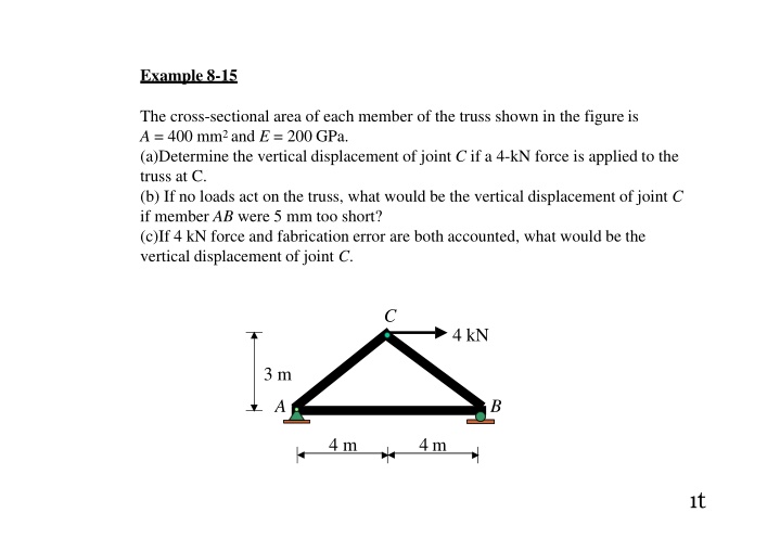
Example 8-15 The cross-sectional area of each member of the truss shown in the figure is A = 400 mm2 and E = 200 GPa. (a)Determine the vertical displacement of joint C if a 4-kN force is applied to the truss at C. (b) If no loads act on the truss, what would be the vertical displacement of joint C if member AB were 5 mm too short? (c)If 4 kN force and fabrication error are both accounted, what would be the vertical displacement of joint C. C 4 kN 3 m A B 4 m 4 m t
SOLUTION Part(a) Virtual Force n. Since the vertical displacement of joint C is to be determined, only a vertical l kN load is placed at joint C. The n force in each member is calculated using the method of joint. Real Force N. The N force in each member is calculated using the method of joint. 1 kN C 4 kN C 4 kN A 0.667 2 0 B B A n (kN) N(kN) 0.5kN 0.5kN 1.5kN 1.5kN a
1 kN C C 4 kN C B BA B A A 0.667 2 8 n (kN) N (kN) = L (m) C B A 10.67 nNL (kN2 m) CV) = nNL (1kN)( AE 10.67 kN m 1( 10.41+10.41+10.67) = = CV (400 10 6m2)(200 106kN) AE m2 CV = +0.133mm, 1
Part (b): The member AB were 5 mm too short 1 kN C A 0.667 B n (kN) 5 mm (1)( CV ) = n( L) =(0.667)( 0.005) CV CV = -3.33mm, Part (c): The 4 kN force and fabrication error are both accounted. CV = 0.133 - 3.33 = -3.20mm CV = -3.20mm, 8
Example 8-16 Determine the vertical displacement of joint C of the steel truss shown. The cross-section area of each member is A = 400 mm2 and E = 200 GPa. F E 4 m D A C B 4 m 4 m 4m 4 kN 4 kN a
SOLUTION Virtual Force n. Since the vertical displacement of joint C is to be determined, only a vertical l kN load is placed at joint C. The n force in each member is calculated using the method of joint. Real Force N. The N force in each member is calculated using the method of joint. F -0.333 E F E -4 0.333 1 0.667 4 m 4 m 4 4 0A 0A 0.333 4 4 4 0.667 D D C C B B 4 m 4 m 4 m 4 m 4 m 4 m 0.333kN 1 kN0.667 kN n (kN) 4 kN 4 kN 4 kN 4 kN N(kN) zo
F E F E F-0.333 E 4 -4 0.333 1 0.667 4 4 4 4 - 4 4 4 4 4 4 0.333 0.667 B C C B B C D A D A DA L(m) n (kN)1 kN 4kN N(kN) 4 kN = F 5.33 E 5.33 16 10.67 5.33 10.67 B C A D nNL(kN2 m) CV) = nNL (1kN)( AE 72.4 kN m 1[(15.07+3(5.33)+2(10.67)+16+30.18)]= = CV (400 10 6m2)(200 106kN) AE m2 = 1.23 mm, z CV
Example 8-17 Determine the vertical displacement of joint C of the steel truss shown. Due to radiant heating from the wall, members are subjected to a temperature change: member AD is increase +60oC, member DC is increase +40oC and member AC is decrease -20oC.Also member DC is fabricated 2 mm too short and member AC 3 mm too long. Take = 12(10-6) , the cross-section area of each member is A = 400 mm2 and E = 200 GPa. wall D C 10 kN 3 m B A 20kN 2 m zz
SOLUTION Due to loadingforces. 1 kN 1 kN 20 kN 10 kN C 0.667kN 23.33kN D 0.667 D 23.33 C D 2 C 1 20 3 m 3 m 3 0 20 3 0 0 2 B B B 2 m A 2 m A 0.667kN 13.33kN A 20 kN L (m) N (kN) n (kN) D 31.13 C nNL AE (1kN)( ) = CV 60 0 1 = (60+31.13+104.12) 0 CV (400)(200) B A CV= 2.44 mm, nNL(kN2 m) zs
1 kN C D D D 0.667 D +40 2 C C C -2 1 +60 3 3 0 2 0 B B B B A A A A T (oC) L (m) n (kN) Fabrication error (mm) Due to temperature change. (1kN)( CV) = n ( T)L = (12 10 6)[(1)(60)(3)+(0.667)(40)(2)+( 1.2)( 20)(3.61)] = 3.84 mm, CV Due to fabrication error. (1kN)( CV) = n( L) = (0.667)( 0.002)+( 1.2)(0.003) = 4.93mm, CV Total displacement . z 4 ( CV)Total= 2.44+3.84 4.93=1.35 mm,
Method of Virtual Work : Bending d M w M C A B d C dx RA RB Virtualloadings ds = d 1 = (m )(d ) = (m ) Mdx L 1 M d = ds C dx EI EI Real displacements zt
Method of Virtual Work : Beams and Frames w w C C A B A B C C RA RB RA RB Virtual loadings Virtualloadings 1 = (m)(d ) = (m ) Mdx 1 = (m )(d ) = (m ) Mdx L L C C EI EI Real displacements Real displacements za
Method of Virtual Work : Beams and Frames Vertical Displacement Realload Virtual unit load w x2 x1 C C A B B A C x2 x1 RA RB 1 RA RB w x1 x2 M2 m 2 M1 m 1 B B x1 V2 v 2 x2 V1 v 1 RB RA RA RB 1 = (m ) Mdx L C EI z 1
Slope Realload Virtual unit couple w x2 x1 1 C C A B B A Cx x1 RA RB 2 RA RB w x2 M2 m 2 M1 m 1 B B x1 V2 v 2 x2 V1 v 1 RB RA RA RB 1 = (m ) Mdx L C EI z 8
Example8-18 The beam shown is subjected to a load P at its end. Determine the slope and displacement at C. EI is constant. P B C A C 2a a za
Displacement at C SOLUTION Virtual Momentm Real MomentM 1 kN P x2 x2 x1 x1 B B A A C C 2a 2a a a 1 2 m P 2 M 3 2 3P 2 = x1 Px m 2 =-x2 m M = -a 1 M2 =-Px2 1 1 2 2 -Pa a ( x2)( Px2)dx2 0 1 C= dx = 2a ( 1 1 m M x 2 Px 2 1)( 1 )dx1+ EI EI EI L 0 2a a 8Pa3 Pa3 Pa3 Px3 Px3 3EI +( 2) = C = ( + = 1 ) 12EI 12EI 3EI 3EI 0 a s o
Slope at C Virtual Momentm x1 Real MomentM x2 P x2 1 kN m x1 B B A A C C 2a 2a a a 1 1 P 2 M 3P 2a m 2a 2 = x1 Px m M11 = 1 1 1 -1 M2 =-Px2 2a m 2 = 1 2 -Pa a ( 1)( Px2 )dx2 (1 kN m)( C ) = dx = 2a ( L m M 1 1 x 2a a Px 2 1)( 1)dx1+ EI EI EI 0 x3 3 0 0 2a 2 1 8a3 3 1 1 1 7 Pa2 ( P 4a P 4a Px Pa2 2 C = ( +( = ( )+( ) = )( 2) )( )( )( ), )( )(1) 2 6 EI EI EI EI EI 0 0 s
Conclusion P B C A C C 2a a Pa3 C =3EI 2 =7 Pa ( ), C 6 EI sz


: The member AB were 5 mm too short")