Tunnel Length Comparison and Proposal for E-Driven Source at ILC
Explore the comparison of tunnel lengths at ILC with an E-driven source and a proposal for a separate tunnel for the E+ source. The analysis shows significant reductions in tunnel lengths with the E-driven source, potentially shortening the construction period.

Download Presentation

Please find below an Image/Link to download the presentation.
The content on the website is provided AS IS for your information and personal use only. It may not be sold, licensed, or shared on other websites without obtaining consent from the author. If you encounter any issues during the download, it is possible that the publisher has removed the file from their server.
You are allowed to download the files provided on this website for personal or commercial use, subject to the condition that they are used lawfully. All files are the property of their respective owners.
The content on the website is provided AS IS for your information and personal use only. It may not be sold, licensed, or shared on other websites without obtaining consent from the author.
E N D
Presentation Transcript
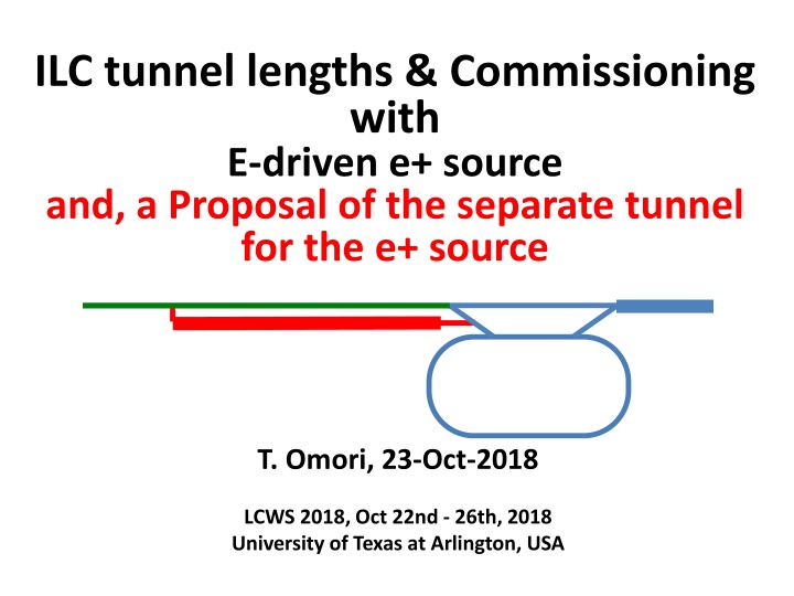
ILC tunnel lengths & Commissioning with E-driven e+ source and, a Proposal of the separate tunnel for the e+ source T. Omori, 23-Oct-2018 LCWS 2018, Oct 22nd - 26th, 2018 University of Texas at Arlington, USA
ILC tunnel lengths E-driven e+ source
Note: Option A A This was called "Option C" by the end of the last year BDS tunnel BDS tunnel geoid geoid laser straight laser straight geoid geoid
with E-driven e+ source Note: Option A A This was called "Option C" by the end of the last year with E-driven e+ source 2361m BDS tunnel BDS tunnel geoid geoid laser straight laser straight geoid geoid with E-driven e+ source 150 m with E-driven e+ remove 3 GeV ML (130m) with E-driven e+ source 150 m With E-driven e+ source, length of electron-BDS becomes significantly shorter (3489m -> 2361 m). with E-driven e+ source Total tunnel length 18.5 km
Tunnel Length Comparison ILC with undulator positron source Option A 31.5 MV/m e-BDS tunnel e+BDS tunnel e-linac tunnel e+linac tunnel laser straight laser straight IP geoid geoid 7.39km 3.49km 2.36km 7.31km total : 20.55 km ILC with E-driven positron source Option A 31.5 MV/m e-BDS tunnel e+BDS tunnel e-linac tunnel e+linac tunnel laser straight laser straight IP geoid geoid 6.88km 2.36km 2.36km 6.88km total : 18.48 km
Option A Note: This was called "Option C" by the end of the last year
Option A Note: This was called "Option C" by the end of the last year with with E-driven e+ source 1500 m E-driven e+ source with E-driven e+ source 490m with E-driven e+ source Total Accelerator tunnel length 18.5 km With E-driven e+ source, length of electron-BDS becomes significantly shorter (3489m -> 2361 m). Access tunnel to the electron-BDS becomes shorter too (690m -> 490 m).
Summary of Tunnel Length (1) With E-driven e+ source, length of several tunnels can be shorter. (2) Total footprint length becomes shorter, 20.5 km -> 18.5 km. (3) Especially length of electron-BDS (where e+ source is located) becomes significantly shorter (3489m -> 2361 m). (4) The access tunnel to the electron-BDS becomes shorter too (690m -> 490 m). (5) Both (3) and (4) mean tunnel construction period of electron-BDS can be shorter than that of the baseline design. -> possibility of early commissioning of the central part (source and DR). See next page.
Commissioning strategy with E-driven e+ source
Commissioning Strategy My Proposal (1) E-driven e+ source is independent of the e- main linac. (2) Make use of the short construction period of e-BDS tunnel and the independence, maybe we can start the commissioning of the e+ source earlier than that of main linacs. (3) We would like to make an integrated commissioning strategy of ILC with an integrated tunnel construction plan, in order to start physic run as early as possible.
Construction and Commissioning of e+/e- sources and DR Optimistic plan or materials to trigger discussions year 1 2 3 4 5 6 7 8 9 10 e+ Source Construction preparation production Making Parts Acc. tubues, Magnets Klystrons, Modulators Target, FC, etc. 1.5ys 5ys preparation construction Tunnel construction tunneling, access holes, finishing, water, electricity 5ys 1.5ys 1y Installation Central Part Commissioning sources and DRs ML construction MLs and ML tunnels Global Commissioning with ML 1.5y 9ys (ML tunnel const. + ML const.) 1y year 1 2 3 4 5 6 7 8 9 10
Summary of Commissioning Strategy My Proposal (1) What I showed today is just to trigger discussions. (2) We would like to make an integrated commissioning strategy of ILC with an integrated tunnel construction plan, in order to start physic run as early as possible.
E-driven e+ source in a Separate tunnel Thanks to Hayano-san and Miyahara-san
Option A Note: This was called "Option C" by the end of the last year with with E-driven e+ source 1500 m E-driven e+ source with E-driven e+ source 490m with E-driven e+ source Total Accelerator tunnel length 18.5 km With E-driven e+ source, length of electron-BDS becomes significantly shorter (3489m -> 2361 m). Access tunnel to the electron-BDS becomes shorter too (690m -> 490 m).
Option A Note: This was called "Option C" by the end of the last year with with E-driven e+ source 1500 m E-driven e+ source with E-driven e+ source 490m with E-driven e+ source Total Accelerator tunnel length 18.5 km Close up -> next page With E-driven e+ source, length of electron-BDS becomes significantly shorter (3489m -> 2361 m). Access tunnel to the electron-BDS becomes shorter too (690m -> 490 m).
PM-8 Close up view of the central part AT-8 490m Interaction Region AT DR (access point to DR) 763m AT DH (branch to detector hall) 693m PM+8 AT+8 283m
PM-8 AT-8 490m the triangular prism shows the slope of the surface PM+8 AT+8 283m
Shared tunnel plan E-Driven e+ source Shared tunnel plan (current plan)
Separate tunnel plan with additional access tunnel cost of access tunnel needed E-Driven e+ source additional access to the surface cost of access tunnel needed
Separate tunnel plan parallel to e- BDS tunnel We choose this a working assumption today. E-Driven e+ source looks reasonable -> working assumption
Shared tunnel plan and Separate tunnel plan Shared tunnel plan e- BDS tunnel (L=2.3 km, w =14 m) put e-Driven e+ source in the BDS tunnel Separate tunnel plan e- BDS tunnel (L=2.3 km, w =7.5 m) e-Driven e+ source tunnel (L=1.1 km, w =9 m)
Shared tunnel plan and Separate tunnel plan Shared tunnel plan e- BDS tunnel (L=2.3 km, w =14 m) put e-Driven e+ source in the BDS tunnel e-Driven e+ soure, RTML, BDS are located. undulator e+ source will be added later. RTML and BDS are located. later, tunnel will be widen and undulator e+ source will be added Separate tunnel plan e- BDS tunnel (L=2.3 km, w =7.5 m) e-Driven e+ source tunnel (L=1.1 km, w =9 m)
Shared tunnel plan and Separate tunnel plan Shared tunnel plan e- BDS tunnel (L=2.3 km, w =14 m) put e-Driven e+ source in the BDS tunnel e-Driven e+ soure, RTML, BDS are located. undulator e+ source will be added later. (a) cost down RTML and BDS are located. later, tunnel will be widen and undulator e+ source will be added Separate tunnel plan e- BDS tunnel (L=2.3 km, w =7.5 m) e-Driven e+ source tunnel (L=1.1 km, w =9 m) (b) cost up very rough estimation: (a) + (b) ~ 0
Separate tunnel plan e- BDS tunnel (L=2.3 km, w =7.5 m) Service Tunnel 3 m Shield 1.5 m 7.5 m RTML 3 m BDS e-Driven e+ source tunnel (L=1.1 km, w =9 m) Service Tunnel 3.5 m Shield 1.5 m 9 m e+ Source Tunnel 4 m
Summary of Separate tunnel My Proposal (1) What I showed today is just to trigger discussions. (2) Separate tunnel for e-Driven e+ source has potential to make early commissioning easier. (3) We can make BDS tunnel (L=2.3 km) narrower (w= 14 m -> 7.5m). The cost down by the narrow BDS tunnel probably compensate the cost up by making a separate tunnel (L=1.1 km, w=9 m) for the e+ source. (we need detailed study)
Polarization Upgrade If we start with the E-driven e+ source, we need an upgrade path to the undulator source. The question is "Can we have it?" Especially, can we have it when we start with shorten BDS tunnel?
Polarization Upgrade If we start with the E-driven e+ source, we need an upgrade path to the undulator source. The question is "Can we have it?" Especially, can we have it when we start with shorten BDS tunnel? Yes we can. We can put undulator and photon drift in the geoid tunnel. --> Yokoya-san's symmetric laser straight scheme
Polarization Upgrade Yokoya-san's symmetric laser straight scheme Only BDS tunnels are laser straight. Straight part is symmetric wrt the IP Undulator and photon drift (and, of course ML) are in the geoid tunnel.
The END Thank you for your attention.
Note: Option A A This was called "Option C" by the end of the last year
My Proposal and Assumption with E-driven e+ source Make use of the shorter tunnel length and make effort to optimize tunnel construction schedule of near DR (*), we may try to make it possible to start commissioning of e+/e- sources and DR earlier than global commissioning. direction of tunnel construction * Length of DR access tunnel is 763 m. It is half of the longest access tunnel at ML. * Length of DR tunnel is 1500 m. It is shorter than a half section of ML tunnel * Length of DR connecting tunnel is 530 m. * Length of RTML tunnel is 250 m.
K. Yokoya, LCWS2017, 26/Oct., Strasbourg What TDR says In TDR, it is assumed that central region tunnels is finished 1.5 years earlier than main linac tunnels. Then it is assumed that central region commissioning starts 1.5 years earlier than global commissioning. Today, people say that earlier start of central region commissioning is NOT realistic.
Commissioning of the e+ injector system Target Capture Linac (250MeV) E-gun Driver e- Linac (3GeV) e+ Booster Linac (5GeV) e+ DR (5GeV) The Tuning Dump at the end of Driver e- Linac? (very low current) Necessary? Permanent? Temporally? The Tuning Dump at theend of Capture? (at 250 MeV) (very low current) Necessary? Permanent? Temporally? The Tuning Dump at 100 MeV Basic strategy: Commissioning of the entire e+ injector system will be done through e+ source and the e+ DR at once ( No partial commissioning will be performed in the injector system. If we make the commissioning step-by-step for each part ( ), it will rather take long time. However the tuning of very low radiation operation at some part may be useful. Tuning at 100MeV point of the driver e- linac will be useful. How about at the end of the Driver e- Linac? Maybe NOT necessary? How about at the end of the Capture? Maybe NOT necessary? ).


