Types of Lenses and Lens Terminology
Explore the world of lenses and lens terminology, including how light refracts through different types of lenses, producing real or virtual images with various characteristics. Learn about the principal axis, axis of symmetry, focal points, and focal length, along with drawing ray diagrams for predicting image formation.

Download Presentation

Please find below an Image/Link to download the presentation.
The content on the website is provided AS IS for your information and personal use only. It may not be sold, licensed, or shared on other websites without obtaining consent from the author. If you encounter any issues during the download, it is possible that the publisher has removed the file from their server.
You are allowed to download the files provided on this website for personal or commercial use, subject to the condition that they are used lawfully. All files are the property of their respective owners.
The content on the website is provided AS IS for your information and personal use only. It may not be sold, licensed, or shared on other websites without obtaining consent from the author.
E N D
Presentation Transcript
Types of Lenses If you have ever used a microscope, telescope, binoculars, or a camera, you have worked with one or more lenses. A lens is a curved transparent material that is smooth and regularly shaped so that when light strikes it, the light refracts in a predictable and useful way. Most lenses are made of transparent glass or very hard plastic.
Types of Lenses By shaping both sides of the lens, it is possible to make light rays diverge or converge as they pass through the lens. The most important aspect of lenses is that the light rays that refract through them can be used to magnify images or to project images onto a screen.
Types of Lenses Relative to the object, the image produced by a thin lens can be real or virtual, inverted or upright, larger or smaller.
Lens Terminology The principal axis is an imaginary line drawn through the optical centre perpendicular to both surfaces. The axis of symmetry is an imaginary vertical line drawn through the optical centre of a lens.
Lens Terminology Both kinds of lenses have two principal focuses. The focal point where the light either comes to a focus or appears to diverge from a focus is given the symbol F, while that on the opposite side of the lens is represented by F .
Lens Terminology The focal length, f, is the distance from the axis of symmetry to the principal focus measured along the principal axis. Since light behaves the same way travelling in either direction through a lens, both types of thin lenses have two equal focal lengths.
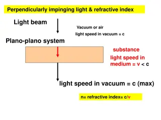
Drawing a Ray Diagram for a Lens A ray diagram is a useful tool for predicting and understanding how images form as a result of light rays emerging from a lens. The index of refraction of a lens is greater than the index of refraction of air
Drawing a Ray Diagram for a Lens The light rays will then bend, or refract, away from the lens surface and toward the normal. When the light passes out of the lens at an angle, the light rays refract again, this time bending away from the normal. The light rays undergo two refractions, the first on entering the lens and the second on leaving the lens
Drawing a Ray Diagram for a Lens A thin lens is a lens that has a thickness that is slight compared to its focal length. An example of a thin lens is an eyeglass lens. You can simplify drawing a ray diagram of a thin lens without affecting its accuracy by assuming that all the refraction takes place at the axis of symmetry.
Concave Lenses A diverging lens is sometimes called a concave lens because it is thinner in the centre than at the edges. As parallel light rays pass through a concave lens, they are refracted away from the principal axis. The light rays diverge and they will never meet on the other side of the lens. The image formed is always upright, virtual and smaller than the object
Drawing a Concave Lens Ray Diagram Any two of the following rays may be used to locate the image: Draw a ray parallel to the principal axis that is refracted through the principal focus (F). 2. Draw a ray that passes through the secondary principal focus (F') and refracts parallel to the principal axis. 3. Draw a ray that passes through the optical center goes straight through, without bending. Only two of these lines are needed to find the image 1.
Drawing a Concave Lens Ray Diagram Step 2 Draw a ray that passes through the secondary principal focus (F') and goes straight through, without bending. Step 1 Draw a ray parallel to the principal axis that is refracted through the principal focus (F). refracts parallel to the principal axis. Step 3 Draw a ray that passes through the optical center F 2F F 2F S: Smaller A: Upright L: In front of F T: Virtual
Convex Lenses A converging lens is also called a convex lens because it is thicker at the centre than at the edges. As parallel light rays travel through a convex lens, they are refracted toward the principal axis. This causes the rays to move toward each other. The light rays cross at the focal point of the lens. Converging lenses are often used as magnifying glasses
Forming a Real Image During Reading Convex lenses are useful because they can form a real image on ascreen. - - The screen must be placed so that the light rays strike it exactly as theyconverge. This way, when the light rays reflect off the screen, they arecoming from a single point. -When the rays from every point on the candle are sent to the screen, a complete image is formed.
Drawing a Convex Lens Ray Diagram Draw a ray that is parallel to the principal axis is refracted through the principal focus (F). 2. Draw a ray that passes through the secondary principal focus (F') is refracted parallel to the principal axis. 3. Draw a ray that passes through the optical center goes straight through, without bending 1. As with converging mirrors, only two rays are required to locate an image. The third one acts as a check
Object between 2F and F Step 1.Draw a ray that is parallel to the principal axis is refracted through the principal focus (F). Step 2. Draw a ray that passes through the secondary principal focus (F') is refracted parallel to the principal axis. Step 3. Draw a ray that passes through the optical center goes straight through, without bending 2F F F 2F S: Larger A: Inverted L: Behind 2F T: Real
Object beyond 2F (An object more than two times the distance of the focal length from the lens) Step 1.Draw a ray that is parallel to the principal axis is refracted through the principal focus (F). Step 2. Draw a ray that passes through the secondary principal focus (F') is refracted parallel to the principal axis. Step 3. Draw a ray that passes through the optical center goes straight through, without bending 2F F F 2F S: Smaller A: Inverted L: Between F and 2F T: Real
Object at 2F 2F F F 2F S: Same size A: Inverted L: At 2F T: Real
Object at F 2F F F 2F NO IMAGE FORMED
Object in front of F 2F F F 2F S: Larger A: Upright L: Behind F T: Virtual