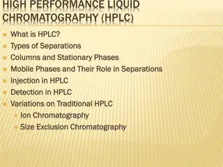
Ultimate HPLC Troubleshooting Guide & Prevention Tips
Learn how to isolate and resolve common HPLC issues with this comprehensive guide. Discover prevention techniques for mobile phase problems, ensuring optimal performance in your HPLC system.

Download Presentation

Please find below an Image/Link to download the presentation.
The content on the website is provided AS IS for your information and personal use only. It may not be sold, licensed, or shared on other websites without obtaining consent from the author. If you encounter any issues during the download, it is possible that the publisher has removed the file from their server.
You are allowed to download the files provided on this website for personal or commercial use, subject to the condition that they are used lawfully. All files are the property of their respective owners.
The content on the website is provided AS IS for your information and personal use only. It may not be sold, licensed, or shared on other websites without obtaining consent from the author.
E N D
Presentation Transcript
HPLC Troubleshooting Guide Sigma Aldrich Bulletin 826E
Isolating HPLC Problems (1) In an HPLC system, problems can arise from many sources. First define the problem, then isolate the source. Use the following Table to determine which component(s) may be causing the trouble. A process of elimination will usually enable you to pinpoint the specific cause and correct the problem.
How to Prevent Mobile Phase Problems (1) Low sensitivity and rising baselines, noise, or spikes on the chromatogram can often be attributed to the mobile phase. Contaminants in the mobile phase are especially troublesome ( ) in gradient elution. The baseline may rise, and spurious peaks ( ) can appear as the level of the contaminated component increases. Water is the most common source of contamination in reversed phase analyses. You should use only high purity distilled or deionized water (HPLC grade) when formulating mobile phases. However, several common deionizers introduce organic contaminants into the water. To remove these contaminants, pass the deionized water through activated charcoal or a preparative C18 column ( ).
How to Prevent Mobile Phase Problems (2) Use only HPLC grade solvents, salts, ion pair reagents, and base and acid modifiers. Cleaning lower quality solvents is time consuming, and trace levels of contaminants often remain. These trace contaminants can cause problems when you use a high sensitivity ultraviolet or fluorescence detector. Because many aqueous buffers promote the growth of bacteria or algae, you should prepare these solutions fresh, and filter them (0.2 m or 0.45 m filter) before use. Filtering also will remove particles that could produce a noisy baseline, or plug the column. Prevent microorganism growth by adding about 100 ppm of sodium azide to aqueous buffers. Alternatively, these buffers may also be mixed with 20% or more of an organic solvent such as ethanol or acetonitrile.
How to Prevent Mobile Phase Problems (3) To prevent bubbles in the system, degas the mobile phase. Generally an in-line degasser is a first choice, but sparging with helium can be an alternative if the mobile phase does not contain any volatile components. Use ion pair reagents carefully. The optimum chain length and concentration of the reagent must be determined for each analysis. Concentrations can be as low as 0.2 mM, or as high as 150 mM, or more. In general, increasing the concentration or chain length increases retention times. High concentrations (>50%) of acetonitrile or some other organic solvents can precipitate ion pair reagents. Also, some salts of ion pair reagents are insoluble in water and will precipitate. Avoid this by using sodium-containing buffers in the presence of long chain sulfonic acids (e.g., sodium dodecyl sulfate), instead of potassium-containing buffers.
How to Prevent Mobile Phase Problems (4) Volatile basic and acidic modifiers, such as triethylamine (TEA) and trifluoracetic acid (TFA), are useful when you wish to recover a compound for further analysis. These modifiers also let you avoid problems associated with ion pair reagents. They can be added to the buffer at concentrations of 0.1 to 1.0% TEA or 0.01 to 0.15% TFA. Increasing the concentration may improve peak shape for certain compounds, but can alter retention times. Recycling the mobile phase used for isocratic separations has become more popular in recent years as a means of reducing the cost of solvents, their disposal, and mobile phase preparation time. An apparatus of Solvent Recovery System uses a microprocessor controlled switching valve to direct the solvent stream to waste when a peak is detected. When the baseline falls under the selected threshold, uncontaminated solvent is directed back to the solvent reservoir.
Isolating Pump Problems The pump must deliver a constant flow of solvent to the column over a wide range of conditions. Modern HPLC pumps incorporate single or dual piston, syringe, or diaphragm pump designs. Pumping system problems are usually easy to spot and correct. Some of the more common symptoms are erratic retention times, noisy baselines, or spikes ( ) in the chromatogram. Leaks at pump fittings or seals ( ) will result in poor chromatography. A sure sign of a leak is a buildup of salts at a pump connection. Buffer salts should be flushed from the system daily with fresh deionized water. To isolate and repair specific problems related to your apparatus, use the troubleshooting and maintenance sections of the operation manual. Pump seals require periodic replacement. You should perform regular maintenance rather than waiting for a problem to occur.
Injector and Injection Solvents (1) The injector rapidly introduces the sample into the system with minimal disruption of the solvent flow. HPLC systems currently use variable loop, fixed loop, and syringe-type injectors. These are activated manually, pneumatically, or electrically. Mechanical problems involving the injector (e.g., leaks, plugged capillary tubing, worn seals ( ) are easy to spot and correct. Use a precolumn filter to prevent plugging of the column frit ( / ) due to physical degradation of the injector seal. Other problems, such as irreproducible injections, are more difficult to solve.
Injector and Injection Solvents (2) Variable peak heights, split peaks ( ), and broad peaks can be caused by incompletely filled sample loops ( ), incompatibility of the injection solvent with the mobile phase, or poor sample solubility. Whenever possible, dissolve and inject samples in mobile phase. Otherwise, be sure the injection solvent is of lower eluting strength than the mobile phase (following Table). Be aware that some autosamplers use separate syringe washing solutions. Make sure that the wash solution is compatible with and weaker than the mobile phase. This is especially important when switching between reversed and normal phase analyses.
Column Protection Although not an integral part of most equipment, mobile phase inlet filters, pre-injector and pre-column filters, and guard columns greatly reduce problems associated with complex separations. We recommend that all samples be filtered through 0.45 m or 0.2 m syringe filters. We strongly recommend the use of guard columns. Filters and guard columns prevent particles and strongly retained compounds from accumulating on the analytical column. The useful life of these disposable products depends on mobile phase composition, sample purity, pH, etc. As these devices become contaminated or plugged with particles, pressure increases and peaks broaden or split. As an example, the following Figure B presents a clear case for the use of guard columns.
Guard Columns Prolong the Lifespan of Your Analytical Columns
Getting the Most from Your Analytical Column (1) Regardless of whether the column contains a bonded reversed or normal phase, ion exchange, affinity, hydrophobic interaction, size exclusion, or resin/silica based packing, the most common problem associated with analytical columns is deterioration ( ). Symptoms of deterioration are poor peak shape, split peaks, shoulders ( ), loss of resolution, decreased retention times, and high back pressure. These symptoms indicate contaminants have accumulated on the frit or column inlet, or there are voids ( ), channels, or a depression ( ) in the packing bed.
Getting the Most from Your Analytical Column (2) Deterioration ( ) is more evident in higher efficiency columns. For example, a 3 micron packing retained by 0.5 micron frits is more susceptible to plugging than a 5 or 10 micron packing retained by 2 micron or larger frits. Proper column protection and sample preparation are essential to getting the most from each column. Overloading ( ) a column can cause poor peak shapes and other problems. Column capacity depends on many factors, but typical values for total amounts of analytes on a column are: Analytical column (25 cm x 4.6 mm) <500 g Semi-preparative column (25 cm x 10 mm) <100 mg Preparative column (25 cm x 21.mm) <500 mg
Solving Detector Problems Detector problems fall into two categories electrical and mechanical/optical. For electrical problems, you should contact the instrument manufacturer. Mechanical or optical problems usually can be traced to the flow cell. Detector-related problems include leaks, air bubbles, and cell contamination. These usually produce spikes or baseline noise on the chromatograms or low sensitivity. Some cells especially those used in refractive index detectors are sensitive to pressure. Flow rates or back pressures that exceed the manufacturer s recommendation will break the cell window. Old or defective ( ) lamps as well as incorrect detector rise time ( ), gain ( ) (,or attenuation ( ) will reduce sensitivity and peak height. Faulty or reversed cable connections can also be the source of problems.
Column Heater, Recorder These components seldom cause problems with the system.
Keeping Accurate Records Most problems don t occur overnight, but develop gradually. Accurate record keeping, then, is vital to detecting and solving many problems. Evaluate every column you receive, when you receive it and at regular intervals thereafter. By keeping a written history of column efficiency, mobile phases used, lamp current, pump performance, etc., you can monitor your system s performance. Records also help prevent mistakes, such as introducing water into a silica column, or precipitating buffer in the system by adding too much organic solvent. Many analysts modify their HPLC systems in some way. Reliable records are the best way to ensure that a modification does not introduce problems. For problems relating to pumps, detectors, automatic samplers, and data systems, consult your instrument manual s troubleshooting guide.
Problem Probable Cause Remedy/Comments Problem No. 1: No Peaks/Very Small Peaks
Problem Probable Cause Remedy/Comments Problem No. 2: No Flow
Problem Probable Cause Remedy/Comments Problem No. 3: No Pressure/Pressure Lower Than Usual
Problem Probable Cause Problem No. 4: Pressure Higher Than Usual Remedy/Comments
Problem Probable Cause Remedy/Comments Problem No. 5: Variable Retention Times
Problem Probable Cause Problem No. 6: Loss of Resolution Remedy/Comments
Problem Probable Cause Problem No. 7: Split Peaks Remedy/Comments
Problem Probable Cause Remedy/Comments Problem No. 8: Peaks Tail on Initial and Later Injections
Problem Probable Cause Problem No. 9: Tailing Peaks Remedy/Comments
Problem Probable Cause Problem No. 10: Fronting Peaks Remedy/Comments
Problem Probable Cause Problem No. 11: Rounded Peaks Remedy/Comments
Problem Probable Cause Problem No. 12: Baseline Drift Remedy/Comments
Problem Probable Cause Remedy/Comments Problem No. 13: Baseline Noise (regular)
Problem Probable Cause Remedy/Comments Problem No. 14: Baseline Noise (irregular)
Problem Probable Cause Problem No. 15: Broad Peaks Remedy/Comments
Problem Probable Cause Remedy/Comments Problem No. 16: Change in Peak Height (one or more peaks)
Problem Probable Cause Problem No. 17: Change in Selectivity Remedy/Comments
Problem Probable Cause Problem No. 18: Negative Peak(s) Remedy/Comments
Problem Probable Cause Problem No. 19: Ghost Peak Remedy/Comments
Restoring Your Columns Performance The following procedures should rejuvenate ( ) a column whose performance has deteriorated due to sample contamination. Disconnect and reverse the column. Connect it to the pump, but not the detector. Follow the appropriate flushing procedure using a flow rate that results in column back pressure of 1500-4500 psi, but never higher than the maximum recommended pressure in the manufacturer s instruction manual. If you have a test mix analyze it according to the conditionslisted on the data sheet. Efficiency, symmetry, and capacity should be within 10-15% of the test sheet values. If not, repack the column inlet or replace the column.
Nonbonded Silica Columns Exposed to Polar Solvent Samples and mobile phases containing very strongly polar solvents, such as water or alcohols, can deactivate uncoated silica HPLC columns. This can drastically affect column performance, particularly solute retention and selectivity. (Figure C2). Even prolonged column flushing with a nonpolar solvent only partially restores column performance, while wasting chemicals. A silica regeneration solution quickly and inexpensively restores silica column performance by removing trapped polar material. Pump the solution through the affected column for 10 minutes at a rate of 4 mL/mi, then flush with mobile phase for 10 min at a rate of 2 mL/min. Evaluate column performance by using the test mixture for evaluating silica columns. Performance should be virtually the same as before the polar solvent was introduced (Figure C3).
Column Test Mixes Performance evaluation mixes for HPLC columns. Well defined test mixes enable you to troubleshoot chromatographic problems, optimize system efficiency, and evaluate columns under conditions where their performance is understood. Test mixes are shipped in amber ampules to prevent photodegradation, and instructions are included for proper use and interpretation of results.
Preventing Leaks Leaks are a common problem in HPLC analyses. To minimize leaks in your system, avoid interchanging hardware and fittings from different manufacturers. Incompatible fittings can be forced to fit initially, but the separation may show problems and repeated connections may eventually cause the fitting to leak. If interchanging is absolutely necessary, use appropriate adapters and check all connections for leaks before proceeding. Highly concentrated salts (>0.2 M) and caustic mobile phases can reduce pump seal efficiency. The lifetime of injector rotor seals also depends on mobile phase conditions, particularly operation at high pH. In some cases, prolonged use of ion pair reagents has a lubricating effect on pump pistons that may produce small leaks at the seal. Some seals do not perform well with certain solvents. Before using a pump under adverse conditions, read the instrument manufacturer s specifications. To replace seals, refer to the maintenance section of the pump manual.
Unclogging () the Column Frit A clogged column frit is another common HPLC problem. To minimize this problem from the start, use a precolumn filter and guard column. To clean the inlet, first disconnect and reverse the column. Connect it to the pump (but not to the detector), and pump solvent throughat twice the standard flow rate. About 5-10 column volumes of solvent should be sufficient to dislodge small amounts of particulate material on the inlet frit. Evaluate the performance of the cleaned column using a standard test mixture.
Replacing a Frit at the Column Inlet Sometimes neither solvent flushing (see above) nor restoration ( ) procedures restore a column s performance. If you ve isolated the column as the problem source, and other restorative procedures have failed, a void ( ) in the packing or a persistent obstruction ( ) on the inlet frit may exist. As a last resort ( ), open the inlet end of the column. Caution: opening the inlet end, and more so opening the outlet end, can permanently damage the packing bed. Before opening columns, consult the manufacturer s literature. (Never open either end of a resin-filled column).

")
")
")
")
")
")


")
")


")
")


 the Column Frit")