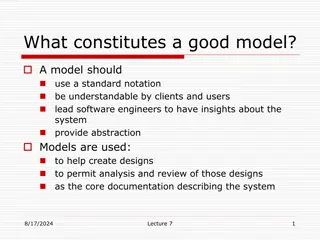
UML Modeling and Component Diagrams for System Architecture
Discover the origins of UML modeling and delve into the significance of component diagrams in architectural modeling. Learn how interfaces play a crucial role in component-based systems and get insights into building component diagrams in StarUML.

Download Presentation

Please find below an Image/Link to download the presentation.
The content on the website is provided AS IS for your information and personal use only. It may not be sold, licensed, or shared on other websites without obtaining consent from the author. If you encounter any issues during the download, it is possible that the publisher has removed the file from their server.
You are allowed to download the files provided on this website for personal or commercial use, subject to the condition that they are used lawfully. All files are the property of their respective owners.
The content on the website is provided AS IS for your information and personal use only. It may not be sold, licensed, or shared on other websites without obtaining consent from the author.
E N D
Presentation Transcript
UML Modeling Object Diagrams Slide 1 Slide 1 Slide 1 Slide 1
References Materials in this educational slide deck are taken from The Unified Modeling Language User Guide. UML stared in October 1994 when Grady Booch and James Rumbaugh worked at Rational Software Company, pioneers in software modeling. These three were the original designers of UML, but they collaborated with partners from the software industry, including Hewlett-Packard, IBM, Oracle and others. Slide 2 Slide 2 Slide 2 Slide 2
UML Component Diagrams Object Diagram Object Diagram An object diagram shows a set of objects and their relationships. Component diagrams are one of the two kinds of diagrams found in modeling the physical aspects of object-oriented systems, also known as architectural modeling architectural modeling. Examples of components include: Executables Database tables Documents Libraries Files A component diagram shows the organization and dependencies among a set of components. Component diagrams are not only important for visualizing, specifying, and documenting component-based systems, but also for constructing executable systems through forward and reverse engineering. Slide 3 Slide 3 Slide 3 Slide 3
Interfaces An interface interface between components is a set of operations performed by a component in the system. A component realizes an interface if it supports the interface; another component then uses (depends on) that interface. Required interfaces: A straight line from the component box with an attached half circle (also represented as a dashed arrow with an open arrow). These symbols represent the interfaces where a component requires information in order to perform its proper function. Provided interfaces: A straight line from the component box with an attached circle. These symbols represent the interfaces where a component produces information used by the required interface of another component. Slide 4 Slide 4 Slide 4 Slide 4
Building a Component Diagram in StarUML (1) stereotype in guillemets Create a Component Diagram Add Components to the Diagram Slide 5 Slide 5 Slide 5 Slide 5
Building a Component Diagram in StarUML (2) Double click the component Add provided interface interfaces (Interface Realization) Slide 6 Slide 6 Slide 6 Slide 6
Building a Component Diagram in StarUML (3) From the components that call the interface, connect a Dependency to the interface The "ball and socket" motif is primarily used today to show interfaces (and their realization) and dependencies dependencies StarUML is touchy. You might have to play with the Line Styles to create pretty balls and sockets. Slide 7 Slide 7 Slide 7 Slide 7
Sample Component Diagram ss Slide 8 Slide 8 Slide 8 Slide 8
Final Thoughts A component is replaceable. A component is substitutable -- it is possible to replace a component with another that conforms to the same interfaces. A well structured component: Provides a crisp abstraction of something drawn from the physical aspect of the system. Provides the realization of a small, well-defined set of interfaces. Is loosely coupled relative to other components; most often, you'll model components only in connection with dependency and realization relationships. Ports Optionally, ports can be used to provide more information. port In this case search.php is using port 3306 to connect to a MySQL database. Slide 9 Slide 9 Slide 9 Slide 9