Learn about the functionality and applications of different types of counters such as asynchronous and synchronous counters, up-down counters, and their features. Explore the concepts of ripple counters, frequency counters, digital clocks, and more in the field of digital electronics.
Please find below an Image/Link to download the presentation.
The content on the website is provided AS IS for your information and personal use only. It may not be sold, licensed, or shared on other websites without obtaining consent from the author. If you encounter any issues during the download, it is possible that the publisher has removed the file from their server.
You are allowed to download the files provided on this website for personal or commercial use, subject to the condition that they are used lawfully. All files are the property of their respective owners.
The content on the website is provided AS IS for your information and personal use only. It may not be sold, licensed, or shared on other websites without obtaining consent from the author.
E N D
Presentation Transcript
Counter Understanding Asynchronous and Synchronous Counters, Up-Down Counters _Nishat Tasnim, Lecturer, CSE, DIU
A counter is a register of counting the number of clock pulses arriving at its clock input. Count Represent the number of clock pulses arrived. One arrival of each clock pulse, the counter is incremented by one. In case of down counter, on arrival of each clock, it is decremented by one. A counter is a sequential circuit that counts pulses or events. It consists of a series of flip-flops connected in a particular sequence. Counters are used in various applications, such as digital clocks, frequency counters, and timers.
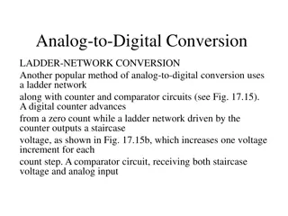
Application of counters Frequency counters Digital clock Time measurement A to D converter Frequency divider circuits Digital triangular wave generator.
Types of Counters Asynchronous (Ripple) Counters: Flip-flops are triggered not simultaneously, but in a ripple effect. Synchronous Counters: All flip-flops are triggered simultaneously by a common clock signal. Up-Down Counters: Capable of counting both upwards and downwards, depending on the control input.
Asynchronous (Ripple) Counters Ripple counter is a cascaded arrangement of flip-flops where the output of one flip-flop drives the clock input of the following flip-flop. The number of flip flops in the cascaded arrangement depends upon the number of different logic states that it goes through before it repeats the sequence a parameter known as the modulus of the counter. A n-bit ripple counter can count up to 2nstates. It is also known as MOD n counter. It is known as ripple counter because of the way the clock pulse ripples its way through the flip-flops. Asynchronous counters are slower than synchronous counters because of the delay in the transmission of the pulses from flip-flop to flip-flop. Asynchronous counters are also called ripple- counters because of the way the clock pulse ripples it way through the flip-flops.
Asynchronous (Ripple) Counters (Cont.) Some of the features of ripple counter are: It is an asynchronous counter. Different flip-flops are used with a different clock pulse. All the flip-flops are used in toggle mode. Only one flip-flop is applied with an external clock pulse and another flip-flop clock is obtained from the output of the previous flip-flop. The flip-flop applied with an external clock pulse act as LSB (Least Significant Bit) in the counting sequence.
Asynchronous (Ripple) Counters (Cont.) A counter may be an up counter that counts upwards or can be a down counter that counts downwards or can do both i.e.count up as well as count downwards depending on the input control. The sequence of counting usually gets repeated after a limit. When counting up, for the n- bit counter the count sequence goes from 000, 001, 010, 110, 111, 000, 001, etc. When counting down the count sequence goes in the opposite manner: 111, 110, 010, 001, 000, 111, 110, etc. A 3-bit Ripple counter using a JK flip-flop is as follows:
Asynchronous (Ripple) Counters (Cont.) In the circuit shown in the above figure, Q0(LSB) will toggle for every clock pulse because JK flip-flop works in toggle mode when both J and K are applied 1, 1, or high input. The following counter will toggle when the previous one changes from 1 to 0. Truth Table is as follows:
Asynchronous (Ripple) Counters (Cont.) Timing diagram Let us assume that the clock is negative edge triggered so the above the counter will act as an up counter because the clock is negative edge triggered and output is taken from Q. Counters are used very frequently to divide clock frequencies and their uses mainly involve digital clocks and in multiplexing. The widely known example of the counter is parallel to serial data conversion logic.
Asynchronous (Ripple) Counters (Cont.) Advantages of Ripple Counter in Digital Logic Can be easily designed by T flip-flop or D flip-flop. Can be used in low speed circuits & divide by n-counters. Used as Truncated counters to design any mode number counters (i.e. Mod 4, Mod 3) Disadvantages of Ripple Counter in Digital Logic Extra flip-flop are needed to do resynchronization. To count the sequence of truncated counters, additional feedback logic is needed. Propagation delay of asynchronous counters is very large, while counting the large number of bits. Counting errors may occur due to propagation delay for high clock frequencies.
Synchronous Counter Unlike the asynchronous counter, synchronous counter has one global clock which drives each flip flop so output changes in parallel. The one advantage of synchronous counter over asynchronous counter is, it can operate on higher frequency than asynchronous counter as it does not have cumulative delay because of same clock is given to each flip flop. It is also called as parallel counter. Eliminates the ripple effect, reducing delay.
Synchronous Counter (Cont.) It can be seen above, that the external clock pulses (pulses to be counted) are fed directly to each of the J-K flip-flops in the counter chain and that both the J and K inputs are all tied together in toggle mode, but only in the first flip-flop, flip-flop FFA (LSB) are they connected HIGH, logic 1 allowing the flip-flop to toggle on every clock pulse. Then the synchronous counter follows a predetermined sequence of states in response to the common clock signal, advancing one state for each pulse. The J and K inputs of flip-flop FFB are connected directly to the output QAof flip-flop FFA, but the J and K inputs of flip- flops FFC and FFD are driven from separate AND gates which are also supplied with signals from the input and output of the previous stage. These additional AND gates generate the required logic for the JK inputs of the next stage.
Synchronous Counter (Cont.) If we enable each JK flip-flop to toggle based on whether or not all preceding flip-flop outputs (Q) are HIGH we can obtain the same counting sequence as with the asynchronous circuit but without the ripple effect, since each flip-flop in this circuit will be clocked at exactly the same time. Then as there is no inherent propagation delay in synchronous counters, because all the counter stages are triggered in parallel at the same time, the maximum operating frequency of this type of frequency counter is much higher than that for a similar asynchronous counter circuit.
Synchronous Counter (Cont.) 4-bit Synchronous Counter Waveform Timing Diagram Because this 4-bit synchronous counter counts sequentially on every clock pulse the resulting outputs count upwards from 0 ( 0000 ) to 15 ( 1111 ). Therefore, this type of counter is also known as a 4-bit Synchronous Up Counter.
Up/Down Counter Capable of counting in both directions: Up Counter: Increments the count Down Counter: Decrements the count. Controlled by a direction input signal (Up/Down control). Commonly used in applications where counting both forward and backward is necessary.
Up/Down Counter State transition diagram for 3 bit up/down counting.
An Up counter is a sequential circuit that counts in ascending order, i.e., from 0 to its maximum value. Operation: On each clock pulse, the counter increments its value by 1. When the maximum count is reached, it wraps around to 0 (in the case of a binary counter). A 3-bit up counter counts from 000 (0) to 111 (7) and then resets to 000. Applications: Frequency division, event counting, timers.
A Down counter is a sequential circuit that counts in descending order, i.e., from its maximum value down to 0. Operation: On each clock pulse, the counter decrements its value by 1. When the count reaches 0, it wraps around to the maximum value. A 3-bit down counter counts from 111 (7) down to 000 (0) and then wraps around to 111. Applications: Countdown timers, reverse event counting, digital clocks.
Heres a brief summary: Synchronous Counters: All flip-flops are triggered simultaneously by the same clock signal, offering faster and more accurate counting due to the elimination of delay effects. Asynchronous (Ripple) Counters: sequentially, creating a ripple effect that causes delays. They are simpler in design but slower in operation. Up/Down Counters: These counters can count both upwards and downwards, controlled by an input signal, making them versatile for applications requiring bidirectional counting. Flip-flops are triggered


 Counters")
 Counters (Cont.)")
 Counters (Cont.)")
 Counters (Cont.)")
 Counters (Cont.)")
 Counters (Cont.)")

")
")
")
")
")