Understanding Behavioral Modeling in Systems Design
Explore the significance of behavioral modeling in system design through topics such as object orientation, dynamic behavior, and use case diagrams. Discover how these concepts help in visualizing and documenting system behavior for effective development and implementation.

Download Presentation

Please find below an Image/Link to download the presentation.
The content on the website is provided AS IS for your information and personal use only. It may not be sold, licensed, or shared on other websites without obtaining consent from the author. If you encounter any issues during the download, it is possible that the publisher has removed the file from their server.
You are allowed to download the files provided on this website for personal or commercial use, subject to the condition that they are used lawfully. All files are the property of their respective owners.
The content on the website is provided AS IS for your information and personal use only. It may not be sold, licensed, or shared on other websites without obtaining consent from the author.
E N D
Presentation Transcript
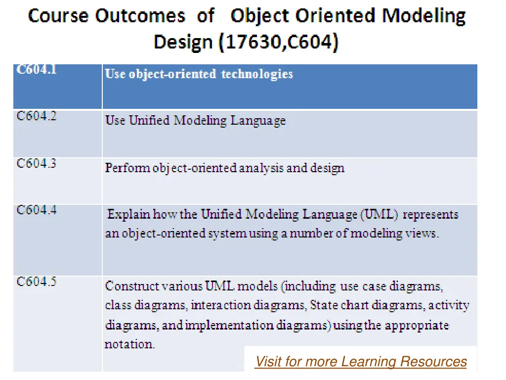
Visit for more Learning Resources Visit for more Learning Resources
3.Basic Behavioral Modeling Object orientation focuses on how data and behavior relate under a single class. Behavioral model describes the interaction in the system.
dynamic behavior means the behavior of the system when it is running /operating. It represents the interaction among the structural diagrams.
Use case diagrams are important in organizing and modeling the behaviors of a system. Use case diagrams used in the UML for modeling the dynamic aspects of systems.
Use case diagrams are important as they are used for visualizing ,specifying, and documenting the behavior of an element. Use case diagrams make system, subsystem and classes understandable.
Use case diagrams designs the functionality of a system using actors and use cases.
Behavioral modeling consist of 1.Sequence diagram 2.Activity diagram 3.Use case diagram 4.State diagram
USE CASE DIAGRAM Use case diagrams are used to describe a set of actions(use cases) that some system should perform with one or more external users of the system i.e actor. Use case diagrams used to visualize the behavior of a system ,so that user can know how to use that element and developers can implement that element.
Use case diagram is a representation of a user s interaction with the system. A use case diagram is a diagram that shows a set of use cases and actors and their relationships.
Purpose of Use case Diagram 1.Used to gather requirements of a system. 2.Used to get an outside view of a system. 3.Identifying external and internal factors influencing the system 4.Use case diagrams are central and major to modeling the behavior of a system, sub system or a class.
Elements of Use cases Subject(Business Boundry) Use cases Actors Dependency Generalization Association relationship
Notations Of Use case 1.Actor: Actor is one who deals with the system. Actor is nothing but users. Actors are responsible for giving input to system and system processes on input. Users use processing output for performing particular action. Notation for actor:
2.Use Cases: Use cases indicates the set of functionalities that helpful to user for achieving the objectives of the system. Oval shape is used to draw use cases. Labels are used with ovals to describe the system s function. PRINT
3.Communication Lines: Communications are shown with the help of lines. 4.System Boundaries: System boundary can be drawn using a rectangle. This box indicates the boundaries of the system. It contains use cases. We need to place actors outside the boundaries of system.
Use case Relationships The Relationship demonstrates relationships between an actor and a use case with the help of simple line.
Order Management System we will find three use cases (Order, SpecialOrder and NormalOrder) and one actor which is customer. The SpecialOrder and NormalOrder use cases are extended from Order use case. So they have extends relationship.
Sequence Diagram Sequence diagram describe interaction among classes. These interactions are modeled as exchanges of messages. These diagrams focus on classes and the message they exchange to accomplish some desired behavior.
A Sequence diagram is an interaction diagram that shows how processes operate with one another and in what order. It is a construct of a Message Sequence Chart. A sequence diagram shows object interactions arranged in time sequence.
Sequence Diagram A sequence diagram demonstrates the elements as they interact over the period of time. A sequence diagram is an interaction diagram that focuses on the time ordering messages.
Sequence diagrams and communication diagrams are known as interaction diagram. These diagrams view the dynamic aspects of the systems.
An interaction diagram shows an interaction ,which is made up of a set of objects and their relationships. 2 types of interaction diagram : 1.Sequence diagram 2.Collaboration diagram
Sequence diagram helps to find out the different participants in the action and their interactions with the sequence of events. Sequence diagrams are useful during testing process.
Notations For Sequence diagram 1.Object/Participants: A sequence diagram is collection of participants. They are parts of the system and they interact with each other during sequence of the operations. Participants are arranged horizontally. Participants should not overlap each other.
2.Times(Lifeline): A sequence diagram shows the order in which the interactions take place in the system. Participant 1
In sequence diagram time starts at the top of the page. In sequence diagram ,time is indicated vertically on the page. Sequence diagrams are all about the order in which interactions between participants takes place and time related information could be shown on timing diagrams.
3.Event: An event can occur at any given point in time when interaction takes place. Events are called as the building blocks for messages. PARTICIPANT 2 PARTICIPANT 1
4.Activation Bars: A message could be sent to a particular participant. When the message is passed ,it gets invokes the receiving participant.
6.Message arrows: An arrowhead that is present on the message ,it helps in understanding what type of message is being passed or sent.
Synchronous message: Synchronous msg are called when the message caller keep waiting for the message receiver to return from invocating message. Message caller Message receiver Communication
Asynchronous message In this the user should not wait and carry on with other work. In this case we use asynchronous message. Ex: printing a document
Structured Control The structure control could be used with sequence diagram that shows different conditions like optional, conditional and parallel loop executions. Systems are not plain and simple. Some or other selections and iterations are part of the system.
Structure control is used to understand and draw the system in such a way that it gives a real feel of the real world.
1.Optional It indicates that if certain condition occurs then either activity is done or it is not done. Suppose there is no any error then only message can be sent or it will not sent.
2.Conditional This control structure works on the result of specific condition. Ex: If bank balance is greater than Rs.5000 then only accept() event will be executed or it will execute different event.
3.Parrallel In some systems we may find that multiple events are happening in parallel. Ex: three events of searching, three search engines are taking place in parallel fashion.
4.Loop Execution Loop could be used for repetitions. It may be specified that what event should occur how many times during drawing sequence diagrams. For more detail contact us For more detail contact us


:")