Understanding Button Debouncing and Finite State Machines in FPGA Development
Explore the concepts of buttons, debouncing, and finite state machines in FPGA development using the Nexys3 board. Learn how to mitigate switch bouncing, synchronize with clocks, and design digital debouncers for optimal performance. Gain insights into the functionality of a finite state machine for implementing a stopwatch application.

Download Presentation

Please find below an Image/Link to download the presentation.
The content on the website is provided AS IS for your information and personal use only. It may not be sold, licensed, or shared on other websites without obtaining consent from the author. If you encounter any issues during the download, it is possible that the publisher has removed the file from their server.
You are allowed to download the files provided on this website for personal or commercial use, subject to the condition that they are used lawfully. All files are the property of their respective owners.
The content on the website is provided AS IS for your information and personal use only. It may not be sold, licensed, or shared on other websites without obtaining consent from the author.
E N D
Presentation Transcript
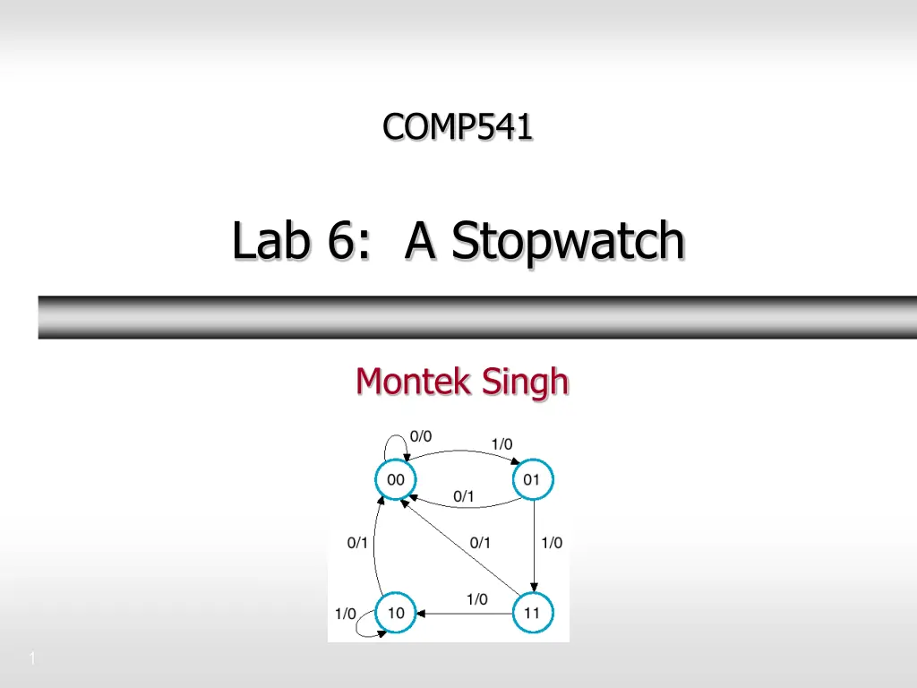
COMP541 Lab 6: A Stopwatch Montek Singh 1
Lab 6 Involves two new concepts: 1. Buttons and Debouncing 2. Finite State Machines 2
Basic I/O The Nexys3 board includes eight slide switches, eight push buttons, eight individual LEDs, and a four digit seven-segment display. The pushbuttons and slide switches are connected to the FPGA via series resistors to prevent damage from inadvertent short circuits (a short circuit could occur if an FPGA pin assigned to a pushbutton or slide switch was inadvertently defined as an output). The pushbuttons are "momentary" switches that normally generate a low output when they are at rest, and a high output only when they are pressed. Slide switches generate constant high or low inputs depending on their position. The eight individual high-efficiency LEDs are anode-connected to the FPGA via 390-ohm resistors, so they will turn on when a logic high voltage is applied to their respective I/O pin. Additional LEDs that are not user-accessible indicate power-on, FPGA programming status, and USB and Ethernet port status. Buttons and Debouncing Mechanical switches bounce vibrations cause them to go to 1 and 0 a number of times called chatter hundreds of times! 3.3V C4 BTNL D9 Buttons BTNR A8 BTNU C9 BTND We want to do 2 things: Debounce : Any ideas? Synchronize with clock i.e., only need to look at it at the next +ve edge of clock B8 BTNS 3.3V T10 SW0 T9 SW1 Think about (for Lab): What does it mean to press the button ? Think carefully!! What if button is held down for a long time? V9 SW2 Slide Switches M8 SW3 3 page 18 of 22 Doc: 502-182
Debouncing Debouncing can be done using analog circuits or digital circuits we will design a digital debouncer Debouncer functionality: cleans up bounces or chatter on inputs input raw bounces several times before settling output clean changes only after raw has settled for a while debouncer raw clean clock 4
Digital Debouncer: Specification Debouncer functionality: cleans up bounces or chatter on inputs input raw bounces several times before settling output clean changes only after raw has settled for a while When the debouncer s raw input is different from its current output ... and consistently so for a number (2N) of clock cycles (several milliseconds) only then update the debouncer output. 5
Finite State Machine for stopwatch Inputs: up, center, down Outputs: countup, paused 6
Meaning of inputs and outputs Inputs: if a button is pressed, the corresponding debounced input is 1 up = 1 up pushbutton is pressed Similarly for center, down At most one button will be pressed Outputs: control the up-down counter s behavior countup = 1 counter will be incrementing countup = 0 counter will be decrementing paused = 1 counter will be frozen paused = 0 counter will be running 7
First attempt Problem: Runs back and forth when pause key pressed 8
Fix Solution: Intermediate states to check for key release 9
Verilog coding style for FSM lab6_fsm_template.sv (posted on the website) 10


