Dive into the world of control signals in hardware design, where instructions are executed based on varying control signal values. Learn how control signals influence hardware behavior and instruction execution. Explore an example circuit design and its dependencies for different types of instructions.
Please find below an Image/Link to download the presentation.
The content on the website is provided AS IS for your information and personal use only. It may not be sold, licensed, or shared on other websites without obtaining consent from the author. If you encounter any issues during the download, it is possible that the publisher has removed the file from their server.
You are allowed to download the files provided on this website for personal or commercial use, subject to the condition that they are used lawfully. All files are the property of their respective owners.
The content on the website is provided AS IS for your information and personal use only. It may not be sold, licensed, or shared on other websites without obtaining consent from the author.
E N D
Presentation Transcript
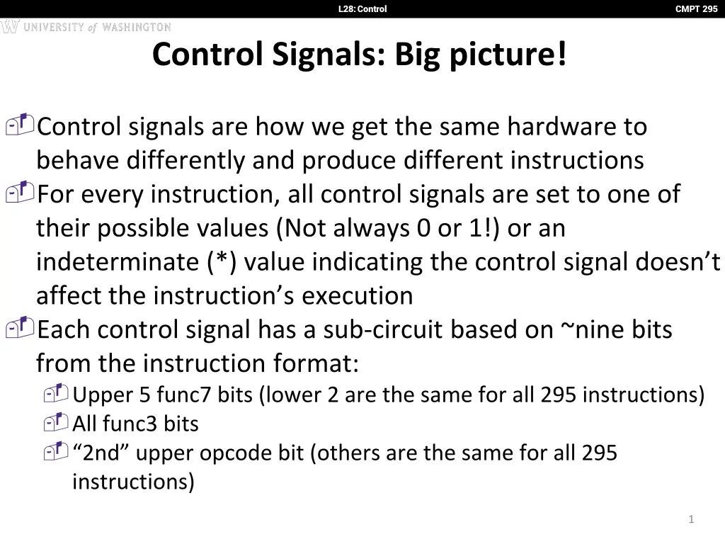
L28: Control CMPT 295 Control Signals: Big picture! Control signals are how we get the same hardware to behave differently and produce different instructions For every instruction, all control signals are set to one of their possible values (Not always 0 or 1!) or an indeterminate (*) value indicating the control signal doesn t affect the instruction s execution Each control signal has a sub-circuit based on ~nine bits from the instruction format: Upper 5 func7 bits (lower 2 are the same for all 295 instructions) All func3 bits 2nd upper opcode bit (others are the same for all 295 instructions) 1
L28: Control CMPT 295 Let s try an example! Design PCSel yourself! I recognise this is hard, given you don t all have logic simulator in front of you :( describe the circuit and its dependencies as best you can ! Might help to split it into three cases: Regular (non-control) instructions Branches Jumps You may assume PCSel = 0 PC = PC + 4, and PCSel = 1 PC = ALUout 2
L28: Control CMPT 295 Control Signals: ADD pc+4 +4 Reg[] pc alu wb 1 DataD 2 ALU Reg[rs1] 1 DMEM alu 0 pc 1 inst[11:7] IMEM AddrD 0 Addr wb Reg[rs2] pc+4 DataR Branch Comp. 0 0 inst[19:15] AddrA DataA DataW mem 1 inst[24:20] AddrB DataB inst[31:7] Imm. Gen imm[31:0] inst[31:0] PCSel ImmSel RegWEn BrUnBrEq BrLT BSel ASel ALUSel MemRW WBSel 3
L28: Control CMPT 295 ADD: Control Signals Here are the signals and values we ve compiled for our ADD instruction: Inst[31:0] BrEq BrLT PCSel ImmSel BrUn ASel BSel ALUSel MemRW RegWEn WBSel * * +4 * * Reg Reg Add Read 1 (Y) ALU add (green = left 3 cols = control INPUTS) (orange = right 9 cols = control OUTPUTS) 4
L28: Control CMPT 295 addi datapath pc+4 +4 Reg[] pc alu wb 1 DataD 2 ALU Reg[rs1] 1 DMEM alu 0 pc 1 inst[11:7] IMEM AddrD 0 Addr wb Reg[rs2] pc+4 DataR Branch Comp. 0 0 inst[19:15] AddrA DataA DataW mem 1 inst[24:20] AddrB DataB inst[31:7] Imm. Gen imm[31:0] inst[31:0] PCSel ImmSel RegWEn BrUnBrEq BrLT BSel ASel ALUSel MemRW WBSel Control Logic Inst[31:0] PCSel ImmSel RegWEn Br Un * Br LT * Br Eq * BSel ASel ALUSel MemRW WBSel +4 I 1 Imm Reg Add Read ALU addi 5
L28: Control CMPT 295 lw datapath pc+4 +4 Reg[] pc alu wb 1 DataD 2 ALU Reg[rs1] 1 DMEM alu 0 pc 1 inst[11:7] IMEM AddrD 0 Addr wb Reg[rs2] pc+4 DataR Branch Comp. 0 0 inst[19:15] AddrA DataA DataW mem 1 inst[24:20] AddrB DataB inst[31:7] Imm. Gen imm[31:0] inst[31:0] PCSel ImmSel RegWEn BrUnBrEq BrLT BSel ASel ALUSel MemRW WBSel Inst[31:0] PCSel ImmSel RegWEn Br Un * Br Eq * Br LT * BSel ASel ALUSel MemRW WBSel +4 I 1 Imm Reg Add Read Mem lw 6
L28: Control CMPT 295 Br datapath pc+4 +4 Reg[] pc alu wb 1 DataD 2 ALU Reg[rs1] 1 DMEM alu 0 pc 1 inst[11:7] IMEM AddrD 0 Addr wb Reg[rs2] pc+4 DataR Branch Comp. 0 0 inst[19:15] AddrA DataA DataW mem 1 inst[24:20] AddrB DataB inst[31:7] Imm. Gen imm[31:0] inst[31:0] PCSel ImmSel RegWEn BrUnBrEq BrLT BSel ASel ALUSel MemRW WBSel Inst[31:0] PCSel ImmSel RegWEn Br Un * Br Eq 0 Br LT * BSel ASel ALUSel MemRW WBSel +4 B 0 Imm PC Add Read * beq ALU B 0 * 1 * Imm PC Add Read * beq 7
L28: Control CMPT 295 Jal datapath pc+4 +4 Reg[] pc alu wb 1 DataD 2 ALU Reg[rs1] 1 DMEM alu 0 pc 1 inst[11:7] IMEM AddrD 0 Addr wb Reg[rs2] pc+4 DataR Branch Comp. 0 0 inst[19:15] AddrA DataA DataW mem 1 inst[24:20] AddrB DataB inst[31:7] Imm. Gen imm[31:0] inst[31:0] PCSel ImmSel RegWEn BrUnBrEq BrLT BSel ASel ALUSel MemRW WBSel Inst[31:0] PCSel ImmSel RegWEn Br Un * Br Eq * BrLT BSel ASel ALUSel MemRW WBSel ALU J 1 * Imm PC Add Read PC+4 jal 8
L28: Control CMPT 295 Inst[31:0] PCSel ImmSel RegWEn Br Un * Br Eq * Br LT * BSel ASel ALUSe l Reg MemRW WBSel +4 * 1 (Y) Reg Add Read ALU add +4 * 1 * * * Reg Reg Sub Read ALU sub +4 * 1 * * * Reg Reg (Op) Read ALU (R-R Op) +4 I 1 * * * Imm Reg Add Read ALU addi +4 I 1 * * * Imm Reg Add Read Mem lw +4 S 0 (N) * * * Imm Reg Add Write * sw +4 B 0 * 0 * Imm PC Add Read * beq ALU B 0 * 1 * Imm PC Add Read * beq ALU B 0 * 0 * Imm PC Add Read * bne +4 B 0 * 1 * Imm PC Add Read * bne ALU B 0 0 * 1 Imm PC Add Read * blt ALU B 0 1 * 1 Imm PC Add Read * bltu ALU I 1 * * * Imm Reg Add Read PC+4 jalr ALU J 1 * * * Imm PC Add Read PC+4 jal +4 U 1 * * * Imm PC Add Read ALU auipc 9
L28: Control CMPT 295 Agenda Quick Datapath Review Control Implementation Performance Analysis Pipelined Execution Pipelined Datapath 10
L28: Control CMPT 295 Instruction Timing IF ID EX MEM WB Total IMEM Reg Read ALU DMEM Reg W 200 ps 100 ps 200 ps 200 ps 100 ps 800 ps 11
L28: Control CMPT 295 Instruction Timing Instr add beq jal lw sw IF = 200ps X X X X X ID = 100ps X X X X X ALU = 200ps X X X X X MEM=200ps WB = 100ps X Total 600ps 500ps 600ps 800ps 700ps X X X X Maximum clock frequency fmax = 1/800ps = 1.25 GHz Most blocks idle most of the time! ex. IF active every 600ps Instruction 1 Instruction 2 IF ID ALU MEM WB IF ID ALU MEM WB Cl k
L28: Control CMPT 295 Performance Measures In our example, CPU executes instructions at 1.25 GHz 1 instruction every 800 ps Can we improve its performance? What do we mean with this statement? Not so obvious: Quicker response time, so one job finishes faster? More jobs per unit time (e.g. web server returning pages)? Longer battery life? 13
L28: Control CMPT 295 Iron Law of Processor Performance Time = Instructions Program Program * Instruction * Cycle Cycles Time 14
L28: Control CMPT 295 Speed Trade-off Example For some task (e.g. image compression) Processor A 1 Million 2.5 2.5 GHz 1 ms Processor B 1.5 Million 1 2 GHz 0.75 ms # Instructions Average CPI Clock rate f Execution time Processor B is faster for this task, despite executing more instructions and having a lower clock rate! Why? Each instruction is less complex! (~2.5 B instructions = 1 A instruction) 15
L28: Control CMPT 295 Agenda Quick Datapath Review Control Implementation Administrivia Performance Analysis Pipelined Execution Pipelined Datapath 16
L28: Control CMPT 295 Pipelined Laundry 2 AM 12 6 PM 1 8 7 11 10 9 T a s k Time 30 30 30 30 30 30 30 M B O r d e r N A Pipelined laundry takes 3.5 hours for 4 loads! 1 load finishes every half hour (after the first load, which takes 2 hours) 17
L28: Control CMPT 295 Pipelining Lessons (1/2) Pipelining doesn t decrease latency of single task; it increases throughput of entire workload Multiple tasks operating simultaneously using different resources Potential speedup ~ number of pipeline stages Speedup reduced by time to fill and drain the pipeline: 8 hours/3.5 hours which gives 2.3X speedup v. potential 4X in this example 6 PM 7 8 9 Time T a s k 30 30 30 30 30 30 30 M B O r d e r N A 18
L28: Control CMPT 295 Pipelining with RISC-V tinstruction instruction sequence add t0, t1, t2 or t3, t4, t5 sll t6, t0, t3 tcycle Single Cycle tstep= 100 200 ps Register access only 100 ps = tcycle = 800 ps 1/800 ps = 1.25 GHz Pipelining tcycle = 200 ps All cycles same length 1000 ps 1/200 ps = 5 GHz Timing Instruction time, tinstruction Clock rate, fs 19
L28: Control CMPT 295 RISC-V Pipeline tinstruction = 1000 ps Resource use in a particular time slot add t0, t1, t2 Resource use by instruction over time or t3, t4, t5 instruction sequence slt t6, t0, t3 sw t0, 4(t3) lw t0, 8(t3) tcycle = 200 ps addi t2, t2, 1 20
L28: Control CMPT 295 Each stage operates on different instruction add t0, t1, t2 lw t0, 8(t3) sw t0, 4(t3) slt t6, t0, t3 or t3, t4, t5 pcM pcX pcF pcD +4 +4 Reg[] rs1X DataD ALU 1 DMEM aluX AddrD 0 Addr aluM DataR Branch Comp. pcF+4 IMEM DataA AddrA DataW DataB AddrB instD rs2M rs2X immX Imm. instX instM instW Pipeline registers separate stages, hold data for each instruction in flight 21
L28: Control CMPT 295 Instruction Level Parallelism (ILP) Pipelining allows us to execute parts of multiple instructions at the same time using the same hardware! This is known as instruction level parallelism Later: Other types of parallelism DLP: same operation on lots of data (SIMD) TLP: executing multiple threads simultaneously (OpenMP) 22
Question: Assume the stage times shown below. Suppose we remove loads and stores from our ISA. Consider going from a single-cycle implementation to a 4-stage pipelined version. Instr Fetch 200ps Reg Read ALU Op Mem Access Reg Write 100 ps 200ps 200ps 100 ps 1) 2) The latency will be 1.25x slower. The throughput will be 3x faster. 1 2 No mem access throughput: (IF+ID+EX+WB) = 600 (4*max_stage)/4 = 200 old/new = 600/200 = 3x faster F F T T F T F T (A) (B) (C) (D) 23
Question: Assume the stage times shown below. Suppose we remove loads and stores from our ISA. Consider going from a single-cycle implementation to a 4-stage pipelined version. Instr Fetch 200ps The latency will be 1.25x slower. The throughput will be 3x faster. Reg Read ALU Op Mem Access Reg Write 100 ps 200ps 200ps 100 ps 1) 2) 1 2 No mem access! Latency: IF+ID+EX+WB = 600 4*max_stage = 800 old/new = 600/800 = negative speedup! 800/600 = 1.33x slower! F F T T F T F T (A) (B) (C) (D) 24
Question: Assume the stage times shown below. Suppose we remove loads and stores from our ISA. Consider going from a single-cycle implementation to a 4-stage pipelined version. Instr Fetch 200ps Reg Read ALU Op Mem Access Reg Write 100 ps 200ps 200ps 100 ps 1) 2) The latency will be 1.25x slower. The throughput will be 3x faster. 1 2 F F T T F T F T (A) (B) (C) (D) 25
L28: Control CMPT 295 Summary Implementing controller for your datapath Ask yourself the questions on the beginning slides! Work in stages, put everything together at the end! Pipelining improves performance by exploiting Instruction Level Parallelism 5-stage pipeline for RV32I: IF, ID, EX, MEM, WB Executes multiple instructions in parallel Each instruction has the same latency, but there s better throughput Think: what problems does pipelining introduce? (more on this next lecture) 26