Understanding DC Resistances in Transformers: Important Considerations
Learn about the crucial factors to consider regarding DC resistances in transformers, including measurement temperatures, winding diagrams, and other essential considerations. This detailed presentation provides valuable insights for evaluating transformer performance and reliability.

Download Presentation

Please find below an Image/Link to download the presentation.
The content on the website is provided AS IS for your information and personal use only. It may not be sold, licensed, or shared on other websites without obtaining consent from the author. If you encounter any issues during the download, it is possible that the publisher has removed the file from their server.
You are allowed to download the files provided on this website for personal or commercial use, subject to the condition that they are used lawfully. All files are the property of their respective owners.
The content on the website is provided AS IS for your information and personal use only. It may not be sold, licensed, or shared on other websites without obtaining consent from the author.
E N D
Presentation Transcript
GIC Model Transformer DC Resistances Important Considerations September 26, 2016 Restricted Distribution
Disclaimer This presentation is being provided for informational purposes only and does not purport to be comprehensive. Neither CenterPoint Energy, Inc., together with its subsidiaries and affiliates (the Company ), nor its employees or representatives, make any representation or warranty (express or implied) relating to this information. By reviewing this presentation, you agree that the Company will not have any liability related to this information or any omissions or misstatements contained herein. You are encouraged to perform your own independent evaluation and analysis. Restricted Distribution 2
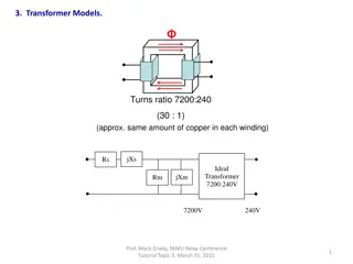
DC Resistance in Autotransformers DC Resistance data values presented in various ways H, X, Y H1-H0, H2-H0, H3-H0, X1-X0, X2-X0, X3-X0, Y1-Y2, Y2-Y3, Y3-Y1 H-X, X-0, Y H1-X1, X1-H0X0, Y1-Y2, etc. HV, XV, YV Series, common, LV Diagrams within the datasheets should supersede all notational norms For the model, values represent common, series, and tertiary resistance values, not high, low, and tertiary winding values for autotransformers (per section 7.2.4 in PSS/E v34 POM) Restricted Distribution 3
Other Considerations Measurement Temperature & Reporting Temperature May only be provided at measurement temperature May only be provided at reported temperature (85 , 75 , etc.) May have both measurement temperature and reported temperature Need to convert to 75 value per NERC Application Guide Rs= resistance at Ts Rm=measured resistance Ts=desired temp. (C ) Tm= measurement temp. (C ) Tk= 234.5 C copper, 225 C aluminum ??+ ?? ??+ ?? ??= ?? **Above eqn. in IEEE C57.152-2013 Resistances provided in per phase versus total Average phase values given for use in submission Must divide total resistance values by 3 to obtain per phase values Resistances provided for tap positions Per NERC Application Guide, values are to be for the neutral tap Restricted Distribution 4
Autotransformer Winding Diagram YNa0d1 H3 Y3 X1 Y2 Y1 X3 H0X0 H1 C S X2 H2 Restricted Distribution 5