Understanding Differences in Control Modes for Converter Designs
Explore the reasons behind discrepancies in equations, waveforms, and current behaviors in DC and non-DC control modes in electronics converter designs. Learn about implications on inductor current, peak current, and Schottky diode selection, as well as analyzing waveforms for correct operation.

Download Presentation

Please find below an Image/Link to download the presentation.
The content on the website is provided AS IS for your information and personal use only. It may not be sold, licensed, or shared on other websites without obtaining consent from the author. If you encounter any issues during the download, it is possible that the publisher has removed the file from their server.
You are allowed to download the files provided on this website for personal or commercial use, subject to the condition that they are used lawfully. All files are the property of their respective owners.
The content on the website is provided AS IS for your information and personal use only. It may not be sold, licensed, or shared on other websites without obtaining consent from the author.
E N D
Presentation Transcript
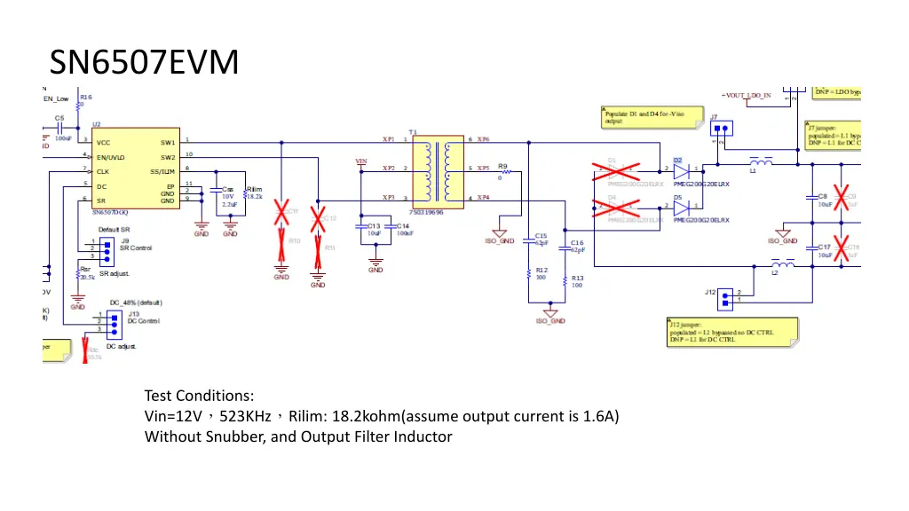
SN6507EVM Test Conditions: Vin=12V 523KHz Rilim: 18.2kohm(assume output current is 1.6A) Without Snubber, and Output Filter Inductor
Probe Setting CH2:SW2_V CH1:SW2_I CH3:SW1_V CH4:SW1_I Vin = 12V Vo = 18.1V No-Load (RDC=51k Duty Control) Vin = 12V Vo = 22.8V No-Load (No RDC) Deadtime is different? Vin = 12V/0.29A Vo = 14.57V Load = 0.2A (RDC=51k Duty Control) Vin = 12V Vo = 15.7V Load = 0.2A No RDC Peak=448mA Peak=900mA 200mA 500mA Peak current is different?
Vin=12V523KHzRilim=18.2kohm(1.6A)Electronics Load = 0.2A Without Snubber and inductor filter CH2:SW2_V CH1:SW2_I CH3:SW1_V CH4:SW1_I Vin = 12V Vo = 15.8V Load = Short circuit
Questions: 1. Why is there a different on equation between DC and non-DC control mode? 2. On the page 2 waveform, we found the deadtime is difference between DC and non-DC mode. How come? And also, the current is 2 times difference in between? Could you help to explain from energy s point of view? 3. On the page 3 waveform, when output rail is shorted to ground, there re always 4 PWM cycles shutting off and then turn on With 4 PWM cycles. In the d/s, it says when short event is happened, PWM will be cycle-by-cycle protection. Is this waveform behavior correct?
Answers: 1. Why is there a different on equation between DC and non-DC control mode? For converter designs with wide-input range but no duty cycle control, the turns ratio needs to take the minimum input voltage into consideration. When Duty Cycle control is enabled, the requirement of turns-ratio doubles as duty cycle is halved from 48% to 25%.
1. Here is a general formula for the inductor current. We still dont figure out why peak current doesnt match this formula from physics perspective as the waveform shown on the page 2. (448mA vs. 900mA) 2. In the formula (21), how device implement it? 3. The reason why customer would like to look into this current is because the Current rating of the Schottky diode needs to be selected correctly when DC is enabled. 1. In page 2, four different waveforms are given 1> Vin = 12V, Vo = 22.8V, No-Load, (No RDC) 2> Vin = 12V, Vo = 18.1V, No-Load, (RDC=51k Duty Control) 3> Vin = 12V, Vo = 15.7V, Load = 0.2A, No RDC 4> Vin = 12V/0.29A, Vo = 14.57V, Load = 0.2A, (RDC=51k Duty Control) Do all this these test are done with a single transformer? Is this a custom build transformer or the same EVM transformer? At which point output voltage are monitored J1 or J8. Is it possible to measure the onload input current with and without RDC. DELTA 04/17: Could you do the EVM simulation with TINA model for below condition: (1) SIM condition is with load or without load? (2) When RDC is enabled for with load and without load 2. The duty cycle feature is be enabled by connecting a resistor RDC on DC pin, and an inductor at the output side. The duty cycle feature is not needed for fixed input designs. The default (pin floating) maximum duty is 48% typical, when DC is enabled based on resistor value it adjust within 48% to 25%. By making the DC pin voltage a function of the input, the duty cycle will adjust with VIN, so that VOUT can be kept constant. The transformer turns ratio needs take this duty cycle into calculation to ensure the expected output voltage level. But care must be taken to make sure that high turns ratios don t lead to primary currents that exceed the specified current limits of the device. 3. Can you please clarify this point. The output rectifier diode current is selected based on output load current. The monitored
2. On the page 2 waveform, we found the deadtime is difference between DC and non-DC mode. How come? And also, the current is 2 times difference in between? Could you help to explain from energy s point of view? The peak current is due to primary inductance of the transformer and the change in on-time duration. Is this deadtime difference observed with same transformer? DELTA 04/17: :it s the same transformer (From DELTA) Can you please reconfirm once, EVM uses Wurth transformer. Or the testing is done with a custom transformer? The change in duty cycle will affect the dead time, the minimum duty cycle is determined by the charge and discharge time of the gate capacitance of Power FETs and the maximum duty cycle is limited by the dead time 70 ns (typical). DELTA 04/17: Could you do the EVM simulation with TINA model for below condition: (1) SIM condition is with load or without load? (2) When RDC is enabled for with load and without load
3. On the page 3 waveform, when output rail is shorted to ground, therere always 4 PWM cycles shutting off and then turn on With 4 PWM cycles. In the d/s, it says when short event is happened, PWM will be cycle-by-cycle protection. Is this waveform behavior correct? This depends on type of short, hard short or soft short. In soft-short the converter goes into hiccup mode on hitting the programmed OCP threshold, the driver will be shut-off for 100 ns (typical), and then retry driving. If the OCP trips again, the cycle continues. It could be a Hard short as it s shorted by Electronics load. Why there re five pulses observed during short circuit? It s about 5MHz/pulse. And in between the pulses, there is a 100ns shut-off time. Is this short-circuit behavior a hiccup mode or cycle by cycle? Could you explain more details! The internal switches are protected with cycle-by-cycle current limit in case of over current. During OCP the device enters in to hiccup mode and shut-off for 100 ns and then retry driving and this cycle continues. DELTA 04/17: : Is this waveform hard short or soft short? Is this in normally operation?


,Electronics Load =")