Understanding Diffraction in X-Ray Analysis
Explore the principles of diffraction in X-ray analysis, including properties of X-rays, high-energy electrons, and neutrons. Learn about diffraction conditions, Laue equations, reciprocal lattice concepts, and experimental techniques in thin film analysis by X-ray scattering.

Download Presentation

Please find below an Image/Link to download the presentation.
The content on the website is provided AS IS for your information and personal use only. It may not be sold, licensed, or shared on other websites without obtaining consent from the author. If you encounter any issues during the download, it is possible that the publisher has removed the file from their server.
You are allowed to download the files provided on this website for personal or commercial use, subject to the condition that they are used lawfully. All files are the property of their respective owners.
The content on the website is provided AS IS for your information and personal use only. It may not be sold, licensed, or shared on other websites without obtaining consent from the author.
E N D
Presentation Transcript
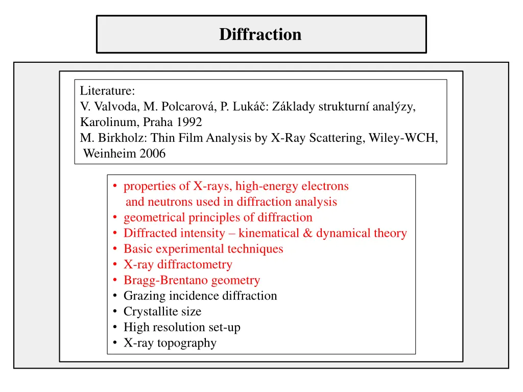
Diffraction Literature: V. Valvoda, M. Polcarov , P. Luk : Z klady strukturn anal zy, Karolinum, Praha 1992 M. Birkholz: Thin Film Analysis by X-Ray Scattering, Wiley-WCH, Weinheim 2006 properties of X-rays, high-energy electrons and neutrons used in diffraction analysis geometrical principles of diffraction Diffracted intensity kinematical & dynamical theory Basic experimental techniques X-ray diffractometry Bragg-Brentano geometry Grazing incidence diffraction Crystallite size High resolution set-up X-ray topography
Properties of X-rays, electrons and neutrons X-rays electrons neutrons charge 0 -e 0 rest mass 0 9.1 10-31kg 1.67 10-27kg energy ~ 10 keV ~ 100 keV ~ 0.03 eV wave length 0.15 nm 0.004 nm 0.12 nm Bragg angles large ~ 1 large extinction length ~ 10 m 0.03 m 100 m absorption length 100 m 1 m 5 cm
Properties of X-rays, electrons and neutrons X-rays electrons neutrons 0.6 rocking curve width 5 0.5 refractive index n < 1 n > 1 n 1 atomic scatt. factors f 10-4nm 1 nm 10-5nm dependence of f on Z ~ Z ~ Z2/3 irregular anomalous dispersion common rare spectral width ~ 1 eV 3 eV 500 eV
diffraction conditions Laue equations a, b, c s s0 Laue equations
Concept of reciprocal lattice scattering vector reciprocal basis vectors reciprocal lattice vectors
Concept of reciprocal lattice conditions for diffraction are fulfilled properties of reciprocal lattice vectors
Looking for solution s/ X-ray tube s0/ 1/
Ewald construction reciprocal lattice Ewald sphere s/ X-ray tube s0/ polycrystalline samples sample 1/ origin of RL Ewald construction is a graphical presentation of the solution of Laue equations
Lattice planes in two-dimensional lattice dhkl dhkl dhkl dhkl
Braggs law diffraction triangle dhkl d sin Miller indices (hkl) diffraction indices hkl 110, 220, 440 (110)
Extinction length Extremely important parameter I0 I depends on hkl, , material I I0 ?? D Dimension of coherent region << kinematical theory Dimension of coherent region dynamical theory
Diffracted intensity Kinematical theory of diffraction 1stBorn approximation hierarchy of scattering calculation of amplitude electron scattering length be(scattering amplitude) [m] ~ classical radius of electron (Thomson) re= 2.82 10-6nm intensity of unpolarized radiation scattered by one free electron
Diffracted intensity atom atomic form factor f integration over the volume of atom absolute units electron units Cromer-Mann coefficients ai, bi, c tabulated electrons X-rays f , f corrections for anomalous dispersion neutrons for electrons
Diffracted intensity unit cell structure factor F(S) summation over all atoms in cell xj, yj, zj fractional coordinates mean squared displacement Debye-Waller factor Bj temperature factors tabulated extinction rules type of lattice, symmetry elements
Structure factor example random occupation Cu Cu3Au alloy 75% Cu 25% Au Au ordered form primitive cubic disordered form fcc quenching from 600 annealing 20 days at 365 and 40 days at 280
Diffracted intensity whole lattice summation over all unit cells interference function for intensity lattice factor intensity scattered by the whole crystal interference function complex number phase factor! electron density fundamental equation
Angular dependence of intensity intensity [atomic factor f(S)]2 Interference function S ~ sin /
YBCO/sapphire 1e5 001 1e4 002 003 1000 Log (Counts) 100 10 6 5 4 3 2 1 0 1 2 3 4 5 6 7 8 9 10 11 12 13 14 15 16 17 18 19 20 21 22 23 24 25 2-Theta - Scale PLDY30_ref - File: PLDY30-do25_ref.raw - Type: 2Th/Th locked - Start: 0.00000 - End: 25.00000 - Step: 0.01000 - Step time: 1. s - Temp.: 25 C (Room) - Time Started: 2 s - 2-Theta: 0.00000 - Theta: 0.00000 Operations: Import
Measured intensity maximum intensity Integral intensity area of the peak for small single crystalline sample phkl= 1 Lp Lorentz-polarization factor for polycrystalline sample phkl= multiplicity factor for small single crystalline sample V irradiated volume for polycrystalline sample quantitative analysis!
Parameters of diffraction peaks FWHM or integral breadth his affected by instrumental broadening g(2 ) crystallite size ~ /(D cos ) (Scherrer equation) microstrain ~ tan planar lattice defects (stacking faults, antiphase boundaries) convolution of line profiles Gaussian Cauchy Lorentz
Dynamical theory of diffraction for (nearly) ideal large single crystals Solution of wave equation in periodic medium (dielectric susceptibility) n = 1 ~ 10-5 10-6 refraction od X-rays multiple diffraction interaction of diffracted and primary beam Intensity I ~ |F(S)|
Rocking curve perfect crystal, Bragg case Darwin curve Prins curve typical values of W: Cu K 1 Mo K 1 3.83 " 0.73 " 8.55 " Si 004, Si 333, GaAs 004, Cu K 1
Debye-Scherrer method measuring of lattice parameters of powder samples with high precision
Laue method orientation of single crystals FMFI UK 1992 Laue 1912
X-Ray diffractometry X-ray sources sealed tubes rotating anodes ~ 18 kW synchrotron ~ 1.5 kW by orders of magnitude higher goniometer measuring the angles with precision ~ 0.0001 PC controll detectors point 0D linear 1D area 2D (films)
Absorption of X-rays t I0 I Lambert-Beer law attenuation coefficient filter
Symmetric /2 (2/) measurement incident beam diffracted beam sample 2 sample surface 2 configurations of diffractometers horizontal or vertical set-up fixed sample, moving X-ray tube and detector ( - ) fixed tube, moving sample ( ) and detector (2 ), ratio of speeds 1:2
Diffraction in symmetric set-up primary beam Diffracting planes parallel to the sample sufrace Each diffraction originates from different assembly of crystallites
Bragg-Brentano set-up focussing circle detector detector slit goniometer axis sample focus of X-ray tube Divergent primary beam irradiates the sample. All beams diffracted at different parts of the sample are focused at the detector slit.
Diffraction pattern of MgB2 wire in Ti sheath 65,000 60,000 55,000 50,000 45,000 40,000 35,000 30,000 25,000 20,000 15,000 10,000 5,000 25.39431 31.94239 59.8235 MgB2 0.00 % MgO Ti 34.15 34.54 0.00 % 0.00 % 36.39065 0 -5,000 -10,000 20 25 30 35 40 45 50 55 60 65 70 75 6,500 6,000 5,500 5,000 4,500 4,000 3,500 3,000 2,500 2,000 1,500 1,000 500 109.6 MgB2 0.00 % MgO Ti 0.00 % 0.00 % 0 -500 -1,000 -1,500 70 75 80 85 90 95 100 105 110 115 120 125 MgB2 and MgO phases are identified. Some peaks of Ti are also present. Red line is the simulated curve provided by software TOPAS 3.0 of Bruker company.


 measurement")