Understanding Failure in Sandwich Joint Plates
Explore a case study on the failure of a sandwich joint plate under axial stress, revealing insights on mitigating sudden failures by incorporating cover plates. Discover the impact of dynamic overstress and the practical solutions to enhance structural integrity.

Download Presentation

Please find below an Image/Link to download the presentation.
The content on the website is provided AS IS for your information and personal use only. It may not be sold, licensed, or shared on other websites without obtaining consent from the author. If you encounter any issues during the download, it is possible that the publisher has removed the file from their server.
You are allowed to download the files provided on this website for personal or commercial use, subject to the condition that they are used lawfully. All files are the property of their respective owners.
The content on the website is provided AS IS for your information and personal use only. It may not be sold, licensed, or shared on other websites without obtaining consent from the author.
E N D
Presentation Transcript
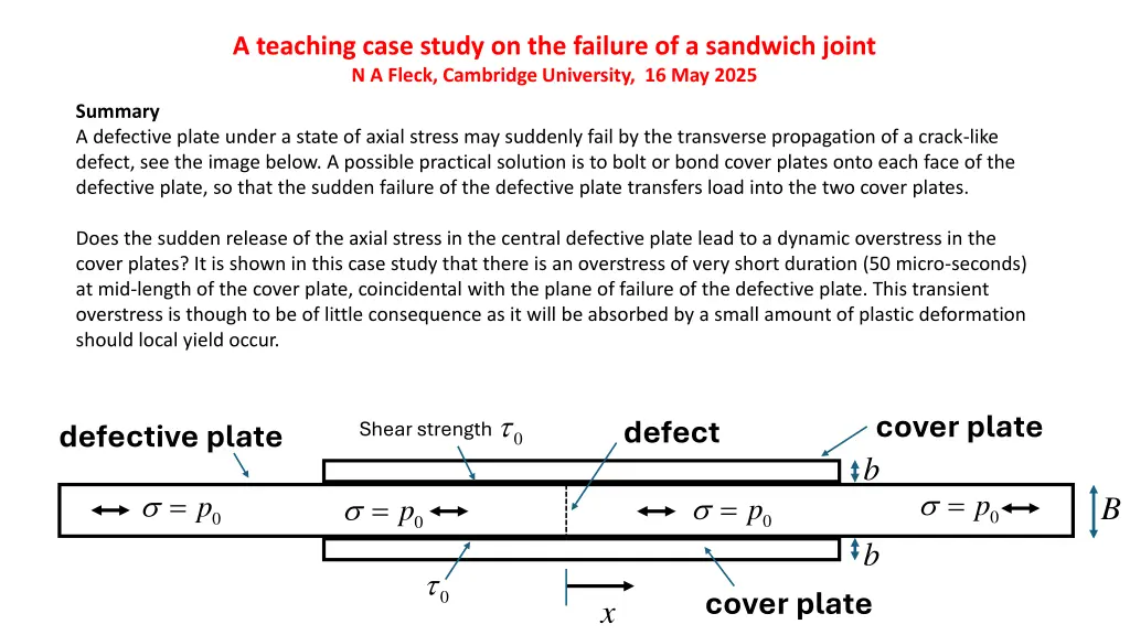
A teaching case study on the failure of a sandwich joint N A Fleck, Cambridge University, 16 May 2025 Summary A defective plate under a state of axial stress may suddenly fail by the transverse propagation of a crack-like defect, see the image below. A possible practical solution is to bolt or bond cover plates onto each face of the defective plate, so that the sudden failure of the defective plate transfers load into the two cover plates. Does the sudden release of the axial stress in the central defective plate lead to a dynamic overstress in the cover plates? It is shown in this case study that there is an overstress of very short duration (50 micro-seconds) at mid-length of the cover plate, coincidental with the plane of failure of the defective plate. This transient overstress is though to be of little consequence as it will be absorbed by a small amount of plastic deformation should local yield occur. cover plate 0 defect Shear strength defective plate b = = 0p = 0p = B 0p 0p b 0 cover plate x
Static shear lag analysis Neglect inertial effects ( ) ( / 2 ) = Bp Peak tensile stress in cover plate = A shear lag zone exists of length 0 0
Static and dynamic shear lag analysis Area fraction of bolts = 0 bolts Friction coefficient Tensile Stress in Bolts Idealise fracture by sudden imposition of a pressure A compressive stress wave propagates in the central plate, and the stress diffuses out into the cover plate to generate tension there. Eventually the solution settles down to steady state.
Idealised model of transient stress in cover plate and flange due to sudden fracture of flange Tensile stress (time) has a peak of 35MPa or 70MPa?? Cover plate, length = 1m Have also used thinner layer, no significant effect of thickness 30mm=b 3mm Jump in Pressure =35 MPa 30mm=B/2 flange plate, length = 3m ?? ??= ?0= 3.5 MPa Poisson ratio = 0 for all layers. Shear modulus GS u/h All elements are linear quadrilateral. Automatic damping is switched off. Shear layer is of height 4 elements, other layers are of height 40 mm Shear layer is of shear modulus GS =1 GPa, density = 40 kg/m3
Elastoplastic interface: tensile axial stress Movie! t = 0.393 ms t = 0.399 ms t = 0.401 ms
Increase shear modulus: ??= 20 GPa t = t2 t = 1.2t2 t = 1.5t2 t = 2t2 t = 2.5t2
Increase shear modulus: ??= 20 GPa t = 3t2 t = 4t2 t = 5t2 t = 6t2 t = 7t2
Compressive outgoing wave is reflected back in the cover plate as a tensile wave B + = CP p Case 2b=B 0 2 B b Tensile wave Static solution Compressive wave
Tensile stress at clamped end of cover plate L = 1 m PEAK xx ? 2?? - static ???= ? xx ????= ? + 2?? - wave ? 2?+ ? ????= ??? ? ? + 2? ? 2?? ???= Static solution
Dynamic magnification factor M in cover plate, associated with the reflected triangular wave at the end of the cover plate, as a function of ? = ?? ? B + = CP p 0 2 B b Peak contribution from tensile triangular wave In addition to static solution


![Comprehensive Case Study on [Insert Case Title Here]](/thumb/159705/comprehensive-case-study-on-insert-case-title-here.jpg)