Learn about how fractures occur in materials under tension and compression testing, with insights on brittle and ductile substances. Explore the different types of fractures, such as tension and shear fractures, and understand the behavior of materials based on brittleness and ductility.
Please find below an Image/Link to download the presentation.
The content on the website is provided AS IS for your information and personal use only. It may not be sold, licensed, or shared on other websites without obtaining consent from the author. If you encounter any issues during the download, it is possible that the publisher has removed the file from their server.
You are allowed to download the files provided on this website for personal or commercial use, subject to the condition that they are used lawfully. All files are the property of their respective owners.
The content on the website is provided AS IS for your information and personal use only. It may not be sold, licensed, or shared on other websites without obtaining consent from the author.
E N D
Presentation Transcript
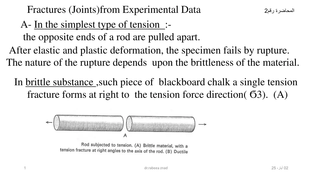
Fractures (Joints)from Experimental Data A- In the simplest type of tension :- the opposite ends of a rod are pulled apart. After elastic and plastic deformation, the specimen fails by rupture. The nature of the rupture depends upon the brittleness of the material. 2 In brittle substance ,such piece of blackboard chalk a single tension fracture forms at right to the tension force direction( 3). (A) 1 25 02 dr.rabeea znad
In more ductile substances , rupture may preceded bynecking that is ,the central part of the rod thins more than the ends.(B) If the tension continued, conical shear fracture developed.in this case the specimen has failed along shear frctures.in some material the rupture is a combination of shear and tension fracture.(c) As conclusion. The same substance behave as brittle near the surface and making a tension fracture at right angle to the tension force direction .where as in depth behave as ductile and making shear fracture 25 02 dr.rabeea znad 2
B-In the simplest type of compression. The test specimen ,usually cylinder or a square prism, is subjected to a compressive force at two opposite ends, and the side are free to expand outward. If the block is a square prism, unconfined on the sides, four sets of shear fracture develop. The four planes parallel to which the fracture form are illustrated in the fig. below. As the compressive force increased, the fracture increase in number and size until one fracture eventually cuts all the way across the specimen and the block collapse. Some sets may be much more extensively developed than others, especially if the specimen lacks homogeneity. 3 25 02 dr.rabeea znad
In many case , specimen under compression fail along fracture parallel to the sides of the prism, from one point of view these are tension fractures, on the principles that the active compression in one direction sets up tensional forces at right angles. This fracture called extension fractures. After load released there are numerous fractures formed at right angle to the axis of compression which called release fracture extension fractures release fracture at right angles to It is tension fractures caused by expansion upon the release. But because there is no active tension ,the called release fracture 7 25 02 dr.rabeea znad
C-the relation of ruptures to couples Fractures develop under couples force are t tension fractures s shear fractures, th thrust faults. t tension ,parallel to diagonal of shortening th thrust faults in the last step of the deformation their strike parallel to long diagonal of the parallelogram. 8 25 02 dr.rabeea znad
Orientation of the maximum paleostress axes Orientation of the maximum paleostress axes can be determined from both conjugate and extension joint sets . Extensional joints form under maximum and minimum principal-stress axes oriented parallel and perpendicular, respectively, to the joint surface (Figure A) ; For conjugate and hybrid joints, the maximum principal-stress axis intersects the acute angle between the two joints, as illustrated in Figure( B,C) 9 25 02 dr.rabeea znad
Diagram showing maximum and minimum principal stress axes for (A) extension joints (B) conjugate shear fractures and (C) conjugate hybrid fractures. List of symbols: 2 , conjugate shear angle; and , maximum and minimum principal stress direction, respectively. 10 25 02 dr.rabeea znad
1-Tension fracture at right angle to the tension force direction. 2- IN confined square prism, two set of fractures developed and dip toward the unconfined sides of the specimen. 3-Release fracture developed at right angle to minimum stress axis. 4-The direction of 1 is the pole to the joint plane which contains the 1 and 3 axes. 5- Name the fractures type in the figure tension ,shear, and thrust fractures 11 25 02 dr.rabeea znad


from Experimental Data")


