Understanding Ideal Transformers in Electrical Engineering
Explore the concept of ideal transformers in electrical engineering, focusing on their characteristics, operations, and applications in circuits. Learn about the turns ratio, dot convention, and transforming loads with transformers.
Download Presentation

Please find below an Image/Link to download the presentation.
The content on the website is provided AS IS for your information and personal use only. It may not be sold, licensed, or shared on other websites without obtaining consent from the author. If you encounter any issues during the download, it is possible that the publisher has removed the file from their server.
You are allowed to download the files provided on this website for personal or commercial use, subject to the condition that they are used lawfully. All files are the property of their respective owners.
The content on the website is provided AS IS for your information and personal use only. It may not be sold, licensed, or shared on other websites without obtaining consent from the author.
E N D
Presentation Transcript
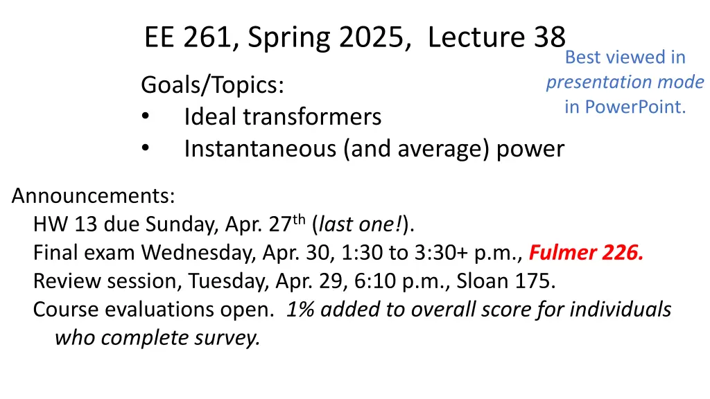
EE 261, Spring 2025, Lecture 38 Best viewed in presentation mode in PowerPoint. Goals/Topics: Ideal transformers Instantaneous (and average) power Announcements: HW 13 due Sunday, Apr. 27th (last one!). Final exam Wednesday, Apr. 30, 1:30 to 3:30+ p.m., Fulmer 226. Review session, Tuesday, Apr. 29, 6:10 p.m., Sloan 175. Course evaluations open. 1% added to overall score for individuals who complete survey.
Phasor Diagram: Parallel Circuit, Variable Capacitor KCL: ? = ??+ ??+ ?? Magnitude of I reduced as |??| gets larger ( 1 ?? gets smaller; ? gets larger). Ideally ??is such that ? is minimized. ? minimum when ??= ?? ? = ?? Magnitude of I reduced as |??| gets larger ( 1 ?? gets smaller; ? gets larger). In general: ? = ? ?
Ideal Transformer Previously consider mutually coupled inductors. Under certain circumstances, in sinusoidal steady state, voltage and current phasors in the inductors (coils) can simply be related by the turns ratio. Requirements: Self inductances are large (infinite). Losses are small (zero). Coupling coefficient is unity (? = 1, ? = ? ?1?2). No ? s or ? or derivatives! Circuit diagram: Although these cannot be exactly achieved, in practice it is possible to get close to these conditions. ?1 and ?2 are the number of turns in each inductor (coil). (Several additional details in textbook but do not directly concern us. See Sec. 9.11.)
?1 ?1 = ?2 Ideal Transformer ?1?1= ?2?2 (2) (1) ?2 Dot convention: If ?1 & ?2have same sign at the dots, use (1) with the positive sign. Otherwise use the negative sign. If ?1 & ?2have same sign at the dots, use (1) with the positive sign. Otherwise use the negative sign. If ?1 & ?2 both directed into or both out of the dots, use (2) with the negative sign. Circuit diagram: 1 ? If ?1 & ?2 both directed into or both out of the dots, use (2) with the negative sign. Otherwise use the positive sign. Otherwise use the positive sign. Turns ratio: ? ?2?1 a?1= ?2 ?1?1= ?1= ??2 (1*) & (2*) or ?2?2 ??1= ?2 For transformer shown here: ?1?1= ?2?2 ?1= ??2 or
Ideal Transformer V1/N1= V2/N2 I1N1=I2N2 I1=a I2 a V1= V2 I1 I2 3 : 7 + - V1 V2 - + a = 1/20 a = 7/3 I1=(1/20) I2 (7/3)V1= V2 I1= (7/3)I2 (1/20)V1=V2
Transforming a Load (Removing transformer.) ?in Zin =V1/ I1 =? Zin =V1/ I1 =? Transformer governing eq. Ohm s law. V2=a V1 I2=V2 / ZL =a V1 / ZL I2=V2 / ZL Zin =ZL / a2 Result is independent of the dots and assumed direction of currents and polarity of voltages! I1=a I2 =a2V1 / ZL I1=a I2 Zin =V1/ I1 = V1/ (a2V1 / ZL) = ZL / a2 Zin =V1/ I1 = V1/ (a2V1 / ZL) Zin =V1/ I1 Turns ratio is the only thing that matters.
Transforming a Load Can use a transformer to match a load to the source circuit for max power transfer. Impedance seen by source: ??+ ?L/?2 Transformers important in many other application (e.g., power distribution).
Consider Same as: I1 I2 a N1 N2 - V2 + ZL V1 IL - + b
?1 Consider What is Zab? A) V1/I1 B) V2/IL C) (V1 + V2)/I1 D) V1/(I1 + I2) ?ab= ?ab?1 + ?ab= ?1+ ?2 ?ab Ohm s law. + ?2 How are I1and I2 related? A) N1I1 = N2I2 B) N1I1 = N2I2 C) I1/N1 = I2/N2 D) I1/N1 = I2/N2 A) I1 + I2 B) I1 I2 C) V2/ZL D) V1/ZL Dot convention for ideal transformer. KCL. ?1= ?2+ ??. KCL. ?1= ?2+ ??. What is IL? Ohm s law.
Consider From previous slide. Zab = (V1 + V2)/I1 (1) N1I1 = N2I2 (2) IL= I1 I2 = V2/ZL (3) V1/N1 = V2/N2 Use (4) in (1) to replace V1: Zab = (N1/N2 + 1) V2 /I1 (5) Use (2) in (3) to replace I2: (1 + N1/N2) I1 = V2/ZL (6) Dot convention ideal transformer. (4) Use (6) to find V2 /I1 and use in (5): Zab = ZL (1+ N1/N2)2
Instantaneous Power Consider a voltage and current in a circuit given by: ? ? = ??cos ?? + ?? ? ? = ??cos ?? + ?? ?? ? ? = ? Shift to a new time axis. Let ? = ? + ?? ? ? ? = ??cos ? ? ? ? = ??cos ? ? ?? ? + ?? = ??cos ?? + ?? ?? ?? ? + ?? = ??cos ?? + ?? ?? ? ? = ??cos ? ? ? ? = ??cos ? ? ?? ? + ?? = ??cos ?? ??+ ?? ?? ? + ?? = ??cos ?? ??+ ?? = ??cos ?? (At ? = 0, current is maximum.) Instantaneous power, ? ? = ? ? ? ? , given by: ? ? = ????cos ?? + ?? ?? cos ??


