Explore the fundamentals of magnetic materials, relative permeability, boundary conditions, and stored energy in electromagnetic systems. Gain insights into the behavior of magnetic fields and their interaction with different materials for applications in electrical engineering.
Please find below an Image/Link to download the presentation.
The content on the website is provided AS IS for your information and personal use only. It may not be sold, licensed, or shared on other websites without obtaining consent from the author. If you encounter any issues during the download, it is possible that the publisher has removed the file from their server.
You are allowed to download the files provided on this website for personal or commercial use, subject to the condition that they are used lawfully. All files are the property of their respective owners.
The content on the website is provided AS IS for your information and personal use only. It may not be sold, licensed, or shared on other websites without obtaining consent from the author.
E N D
Presentation Transcript
ECE 3318 Applied Electricity and Magnetism Spring 2025 Prof. David R. Jackson Dept. of ECE Notes 30 Magnetic Materials and Stored Energy 1
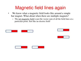
Magnetic Materials B Because of electron spin, atoms tend to acts as little current loops, and hence as electromagnetics, or bar magnets. When a magnetic field is applied, the little atomic magnets tend to line up. This effect is what causes the material to have a relative permeability r. = 0 r 2
Magnetic Materials (cont.) = 0 r Type of Material Nonmagnetic Diamagnetic Paramagnetic Ferrimagnetic Ferromagnetic Property r = 1 r < 1 r > 1 r >> 1 r >> 1 Please see the textbooks to learn more about magnetic materials and permeability. For more information: http://en.wikipedia.org/wiki/Magnetism 3
Magnetic Materials Relative Permeability r 1 1.0000004 0.999992 0.999994 1.00002 0.99998 600 5000 100 2000 50,000 1,000,000 Material Vacuum Air Water Copper Aluminum Silver Nickel Iron Carbon Steel Transformer Steel Mumetal Supermalloy Note: Values can often vary depending on purity and processing. http://en.wikipedia.org/wiki/Permeability_(electromagnetism) 4
Boundary Conditions (Please see the textbooks for a derivation.) Region 1 H n 1 t = B sJ 1 0 1 r 1 n = H B 2 t 2 0 2 r 2 n Region 2 The unit normal vector points towards region 1. ( ) = = n H H J B B 1 2 t t s 1 2 n n = H H Note: If there is no surface current: 1 2 t t 5
Boundary Conditions (cont.) H n t sJ PEC Assume zero magnetic field inside the PEC. = B = n H J 0 t s n Note: For a practical conductor, these BCs will be accurate if the conductivity is high enough so that the skin depth is small. In this case Js models the current flowing within the first few skin depths from the surface. 6
Boundary Conditions (cont.) B PEC B = 0 n Magnetic field lines must bend around a perfect electric conductor (PEC). This is the opposite behavior of electric field lines. E PEC tE = 0 7
Magnetic Stored Energy 1 2 = B H dV U H V = = B H H We also have 0 r Hence, we can write 1 2 = 2 U H dV 0 H r V 8
Example sL Find UH inside solenoid a Assume infinite solenoid approximation. = H z z 0 r 1 2 ( ) 2 = U H dV N turns 0 H r z I V 1 2 ( ) 2 nI dV 0 r N L = V n 1 2 ( ) ( ) 2 = 2 a L nI s 0 s r ( ) 2 = = z nI , H a 1 2 N L = 2 2 a L I 0 s r 0, s a 2 1 2 N L J = 2 2 U a I 0 H r s 9
Finite-Length Solenoid In a practical finite-length solenoid, the magnetic flux density immediately outside the solenoid is usually what is important. sL out z B From BCs: in z B r z = in z out z B B a = 0 N turns I ( ) z nI z nI , H inside The solenoid is long but finite. ( ) , B inside 0 r (from BCs) ( ) Note: out z B nI It is the strength of the B field immediately outside the solenoid that determines the lifting strength of the magnet. A larger value of r makes better electromagnet! 0 r 10
Hysteresis Hysteresis is a nonlinear effect that many magnetic materials exhibit. Hysteresis loop CH z B Linear Material B = r = constant dB dH B H (saturation) 0 max z r z 0 New sample (has never been magnetized) C H H z Nonlinear iron core = , H nI a B z max 11
Hysteresis (cont.) Note: The size of the hysteresis loop depends on the maximum current in the coil. z B Larger maximum current Smaller maximum current H z = , H nI a z 12
Hysteresis (cont.) Hysteresis causes power loss for an AC magnetic field in a nonlinear material (such as in a transformer core). cL z B c A z ( ) i t N turns - + ( ) v t f = frequency [Hz] 13
Hysteresis (cont.) Power going into coil: d dt ( ) ( ) = + = v t N Faraday s law: z ( ) ( ) ( ) v t i t d N dt = p t (+ sign by Lenz s law) ( ) i t = = V A L dB dt dB dt dB dt c c c ( ) i t = NA z = (volume of core) A B c cL c z n n ( ) i t = NA z c z B c A 1 n z = NA H z (area of core) c z 1 n dB dt ( ) ( ) i t = nL A H z N turns c c z dB dt ( ) - + ( ) = A L H z v t c c z dB dt ( ), = H ni t a = V H z z c z 14
Hysteresis (cont.) Energy going into the coil in one cycle of the waveform (period T): T cL ( ) = W p t dt 0 T z B dB dt = V H dt z c A z c z 0 = V H dB c z z ( ) i t N turns C H max B max B = + right z left z V H dB V H dB - + c z c z ( ) v t max B max B max B ( ) = right z left z V H H dB c z max B Note: b ( ) ( ) x ( ) = = y y x dx W V A area between curves 2 1 c h a Ah= area inside hysteresis curve The energy is not zero: there is loss! 15
Hysteresis (cont.) The average power loss (in watts) due to hysteresis is: W T ( ) = = = ave hys P Wf V A f c f We thus have Note: = ave hys P W A f V There would be no hysteresis loss if the core material was linear (Ah = 0). h c where: = e TA/m A area inside hysteresis curv h = Hz f frequency = 3 m V volume of core c 16


")


")
")


")
")
")
")
")