Understanding Matched Filters in Signal Detection
Explore the concept of matched filters in signal detection, where a linear system maximizes the signal-to-noise ratio. Learn about the impulse response, power spectral density, and practical implementation of matched filters for detecting signals in noise.

Download Presentation

Please find below an Image/Link to download the presentation.
The content on the website is provided AS IS for your information and personal use only. It may not be sold, licensed, or shared on other websites without obtaining consent from the author. If you encounter any issues during the download, it is possible that the publisher has removed the file from their server.
You are allowed to download the files provided on this website for personal or commercial use, subject to the condition that they are used lawfully. All files are the property of their respective owners.
The content on the website is provided AS IS for your information and personal use only. It may not be sold, licensed, or shared on other websites without obtaining consent from the author.
E N D
Presentation Transcript
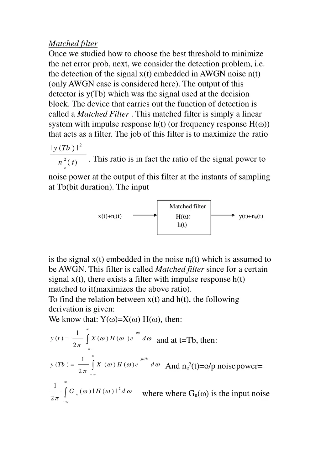
Matched filter Once we studied how to choose the best threshold to minimize the net error prob, next, we consider the detection problem, i.e. the detection of the signal x(t) embedded in AWGN noise n(t) (only AWGN case is considered here). The output of this detector is y(Tb) which was the signal used at the decision block. The device that carries out the function of detection is called a Matched Filter . This matched filter is simply a linear system with impulse response h(t) (or frequency response H( )) that acts as a filter. The job of this filter is to maximize the ratio 2 | y (Tb ) | . This ratio is in fact the ratio of the signal power to n 2 ( t) o noise power at the output of this filter at the instants of sampling at Tb(bit duration). The input Matched filter H( ) h(t) x(t)+ni(t) y(t)+no(t) is the signal x(t) embedded in the noise ni(t) which is assumed to be AWGN. This filter is called Matched filter since for a certain signal x(t), there exists a filter with impulse response h(t) matched to it(maximizes the above ratio). To find the relation between x(t) and h(t), the following derivation is given: We know that: Y( )=X( ) H( ), then: X ( ) H ( )e 1 jwt d y (t ) = and at t=Tb, then: 2 X ( ) H ( )e 1 jwTb d y (Tb ) = And n 2(t)=o/p noisepower= o 2 1 G ( ) | H ( ) | 2 d where where Gn( ) is the input noise n 2
power spectral density which is flat for AWGN and is equal to o/2 (two-sided spectrum), then: 1 2 ( / 2 ) | H ( ) | d o2 n (t)= o 2 The ratio to be maximized will be: H ( ) X ( )e 1 2 jwTb d | | 2 2 | y (Tb ) | = then using Shwartz 2 (t ) o n 1 ( / 2 ) | H ( ) | 2 d o 2 inequality that states that: | f ( x ) f ( x ) dx | 2 ( 1 2 | f ( x ) | 2 dx ) ( | f ( x ) | 2 dx ) where equal 1 2 sign holds if f1(x)=k f2 *(x) (*=conjugate), k is any constant that may represent the gain, say k=1. Now if f1(x)=|H( )|, f2(x)=X( )ejwTb, then applying this inequality on the numerator of above ratio | y(Tb ) |2 1 | X ( ) |2 d And since |ejwTb|2=1, then: n 2 (t) o o and since: 2 | y (Tb ) | E | X ( ) | 2 d = E =energy of x(t),then: or: 2 n (t) o o | y (Tb ) |2 E = [ ]max note that both E and o havethe n 2 (t) o o | y (Tb ) |2 E = [ ]max ( / 2 ) =Max SNR at matchedfilter n 2 (t ) o o output. o=one-sided AWGN spectral density(Watt/Hz).To find the condition for maximization, recall that we used equal sign in Schwartz inequality if f1(x)=f* (x) , or H( )=(X( )ejwTb)*=X*( )e-jwTb, or in time domain: 2
h(t)=x(Tb-t). Hence the impulse response of a matched filter matched to the signal x(t) is the negative time of x(t) shifted by Tb. Ex: Find the impulse response and the max SNR at the o/p of a matched filter used to detect the signal so(t) shown embedded in AWGN with one-sided spectral density of o. h(t) so(t) V V Tb t Tb t Solution: so(t)=(V/Tb) t Then h(t)=so(Tb-t)=(V/Tb)(Tb-t)=V-(V/Tb)t for Tb>t>0. And the max SNR =E/( o/2), where E can also be found from for Tb>t>0 Tb 2 2 Tb 0 V V Tb 2 ( t ) dt = Tb 2 dt = E = the time domain as: , then: s t o 2 3 0 2V 2Tb (SNR)max= . 3 o Practical Implementation of the Matched filter: We know that h(t)=x(Tb-t), and since y(t)=h(t) x(t) ( =convolution) t Tb y(t) = x( )h(t )d 0 y (Tb ) = x ( ) h (Tb ) d 0 and at t=Tb Tb Tb 2 y (Tb ) = x ( ) x (Tb Tb 0 + ) d = x ( t ) dt =Energy of x(t)over 0 Or Tb Above equation indicates that if the i/p x(t) is noise free then y(Tb) is E, but in general if the i/p is x(t)+n(t), then y(Tb) will be a Gaussian random variable (n(t) is Gaussian) with mean E and variance that is linearly proportional to o. The practical implementation can be deduced as the product of the input x(t)+n(t) and x(t) then integrate
the result over t=0 to t=Tb. The figure below shows the practical implementation of the matched t=Tb Y(Tb) x(t)+n(t) x(t) Error probability of binary signal detection using matched filter: Assume that the matched filter is used to detect the binary signal waveforms so(t) and s1(t) embedded in AWGN. Here, we need two matched filters, one matched to so(t) with impulse response ho(t)=so(Tb-t) and the other matched to s1(t) with impulse response h1(t)=s1(Tb-t) Max at so(t) and min ats1(t) Matched filter ho(t) yo(Tb) s(t)+n(t) data Matched filter h1(t) min at s (t) and max at s (t) y1(Tb) o 1 Tb 2(t)dt=mean of yo(Tb)=energy of so(t) =o/p of ho(t) due 0 = E s o o toso(t). Tb 2(t)dt=mean of y1(Tb)=energy of s1(t) =o/p of h1(t) due 0 = E s 1 1 to s1(t) Tb And: E o 1 = s o ( t ) s1 ( t ) dt=cross energy between so(t) and s1(t) 0 =o/p of ho(t) due to s1(t) = o/p of h1(t) due to so(t)
Recall that for equiprobable case p(0T)=p(1T)=0.5, and for Gaussian case, then: Tb [ s ( t ) s ( t )] 0 2dt 1 o + E 2 E E 1 01) o ) = Q ( pe = Q ( 2 2 o o Ex: Matched filter is used to detect the two equiprobable signals shown in AWGN. Find the error prob in terms of average signal power, bit rate, and noise spectral density o. s1(t) Tb o s (t) V t -V Tb t so(t)=-(V/Tb) t over bit duration 0 to Solution: s1(t)=(V/Tb) t, Tb. Tb 2 2 ( V ) V + E 2 E E = 2 dt = 1 01) o E t Tb pe= where: Q ( o 2b 2 3 T o 0 Tb 2 2 V (V ) 2 dt = = T E t Tb and 1 2 b 3 0 Tb 2 V ( V )(V ) 2 dt = = Tb E t o1 T 2b 3 0 And S=average signal power=[0.5Eo+0.5E1]/Tb=V2/3 (V 2 / 3 )Tb + (V 2 / 3 )Tb + ( 2V 2 / 3 )Tb pe = Q{ } , if Rb=bit rate=1/Tb 2 o 2 2V 2S pe = Q{ } = Q ( ) 3 Rb Rb o o Homework: Repeat previous example for unipolar 0,+A signals(orthogonal signals) and bipolar A signals(antipodal signals). 2S S ) ) pe = Q ( pe = Q ( (Ans: for unipolar , for bipolar Rb Rb o o
Error prob for digital carrier systems: [A]-coherent detection with matched filter: 1-ASK (OOK) (ON-OFF) keying: The modulator circuit is Here the two signals are so(t)=0, 1 s (t)=Acos t over bit durationTb Mixer ASK (OOK) data (unipol Power Amplifier ar) Acos c(t) We use the general equation: 0 1 1 0 A + E 2 E E 1 01 o pe=Q ( ) , where forOOK, t 2 o Eo=E01=0,and: Tb Tb Tb Tb ?2 ?? ? 0 E1= (????( ? 0 (1 + ???2 ??)?? = (A2Tb)/2 2 ?)) ??= ? 2 2Tb A pe = Q ( )and to express in terms of average signal power, then: 4 o S=[0.5Eo+0.5E1]/Tb=A2/4, then: S ) . For simplicity,let: pe = Q ( Rb o S Eb = = energy = / bit ). , then: pe = Q ( Rb o o 2-BPSK signals(Binary Phase Shift Keying): ????( ??) =BPSK mixer Bipolarsignal ????( ??)
Here the two signals are so(t)=Acos ?t, s1(t)= Acos(?? + ?)= -Acos?t over bit duration Tb. Again, using the same general equation, then: Eo=E1=[A2Tb]/2 since both so(t) and s1(t) are two sinusoids, also: Tb 2 2 E01= A t dt cos =-[A2Tb]/2. 0 Also S=[0.5Eo+0.5E1]/Tb=A2/2=average signal power, then: 2Tb 2Tb + A 2Tb 2 Tb + 0.5 A [0.5 A A pe = Q( ) = Q( ) 2 o o 2S 2 ) ) = Q ( pe = Q( which is better than OOK. Rb o 3-FSK (frequency shift keying): P S K(f) Here the two signals are : so(t)=Acos 1t, s1(t)=Acos 2t over bit duration Tb. Note that pe depends also on = 2- 1=2 f =2 f f F+ R 2 F2 F-R 1b F1 ? b ? f
( t) 0 1 1 t T b T b T b S1(t) f2 f2 t S2(t) f1 t We write so(t)=A cos[( c-0.5 d) t] and s1(t)=A cos[( c+0.5 d) t], then: Eo=E1=[A2Tb]/2, since the deviation ddoes not affect the power of a sinusoid. In fact, the effect of dappears on the cross energy Eo1given by: Tb 2 = A 0 cos[( c 0 .5 d ) t ] cos[( c + 0 .5 d ) t ]dt E01 Where: Cos(A)COS(B)=1/2[COS(A-B)+COS(A+B)] A 2 Tb 2 A 2 Tb sin Tb = d which is a sinc function as shown: A2 sin Tb [cos t + cos 2 t ] dt = d d = E c 01 2 d 0 E Or o1 Tb 2 d
This has nulls at dTb=, 2, 3,and [Eo1]min=- 0.217(A2Tb/2) at dTb=4.49rad or at fdTb=0.715. Next to find pe, then: 2 Tb ( sin d Tb )] 2 Tb + 0 .5 A 2 Tb A [ 0 .5 A Tb d ) pe = Q( 2 o sin Tb 2 Tb (1 ( sin d Tb)] [S (1 ( d )] [ A Tb Tb d d ) ) pe = Q ( = Q( Rb 2 o o S = Where S=[0.5Eo+0.5E1]/Tb=0.5A2, and if , then: Rb o sin Tb (1 pe = Q ( d )which is a general formula used for Tb d matched filter detection of FSK signals. Special cases in FSK: 1-if dTb= , 2 , 3 ,.., or fd=0.5Rb, Rb, 1.5Rb,... this gives Eo1=0 (orthogonal FSK), and pe = Q ( ).
sin Tb d = 0 .217 2-if dTb=4.49rad, or fd=0.715Rb, then: Tb d And this gives: (optimum)performance of FSK. ) which is thebest pe = Q ( 1.217 Noncoherent detection: Previous equations for error prob of digital carrier systems using matched filter under AWGN can not be used for noncoherent detection(not matched filter). In fact, exact derivation for noncoherent case is mathematically complicated. Approximate results are given without derivations: 1 noncoherentASK(OOK): pe=0.5[e- /2+Q( )] 0.5 e- /2 for >>1, since here e- /2 >>Q( ) 2 noncoherent FSK: pe 0.5 e- /2 for >>1(the same as OOK) 3-noncoherent PSK=DPSK: pe 0.5 e- for >>1 (better than OOK or FSK) Ex: Matched filter detection is used to detect BPSK signals at a rate of 600bps. If transmitted power is 5KW over an HF channel having estimated path losses of 150dB, find the error prob if the noise at detector input has one sided spectral density of 10-15 Watt/Hz. Solution: path loss is the reduction in power (attenuation) of electromagnetic waves : Path loss (L)=PT PT=trans power=5000 W, then, PR=S=PT*10-0.1*L in dB=5000*10-0.1*150 S=5*10-12 W=average signalpower. 5 *10 12 = = = 8 .333, then PR S 10 15 * 600 Rb o 5 2 ) = Q ( pe = Q ( 2 * 8 .3333 ) = Q ( 4 .08 ) 2 * 10
Ex: Pepeat previous example for FSK signals with f1=700Hz, f2=2000Hz. Solution: Here d=2 (2000-700)=2600 , and d Tb=2600 /600=4.3333 , then and for the same =8.333: sin Tb sin 4 .333 3 (1 pe = Q ( ) = Q ( 8 .333 (1 ) = Q ( 2 .84 ) 2 .3 *10 d Tb 4 .333 d Which is worst than BPSK for the same .( remember that both BPSK and FSK have the same average power of A2 /2, but the performance of BPSK is better at the expense of the requirement of carrier recovery at the receiver).


=x(Tb-t).")

=p(1T)=0.5, and for")

=Acos ?t, s1(t)= Acos(??")
")