Understanding Natural Responses in RL and LR Circuits
Delve into the natural responses of RL and LR circuits without DC sources, exploring switching RL circuits, steady-state behavior with DC sources, and the general solutions for these circuits. Learn about the important definitions and concepts related to the natural responses of LR circuits.
Download Presentation

Please find below an Image/Link to download the presentation.
The content on the website is provided AS IS for your information and personal use only. It may not be sold, licensed, or shared on other websites without obtaining consent from the author. If you encounter any issues during the download, it is possible that the publisher has removed the file from their server.
You are allowed to download the files provided on this website for personal or commercial use, subject to the condition that they are used lawfully. All files are the property of their respective owners.
The content on the website is provided AS IS for your information and personal use only. It may not be sold, licensed, or shared on other websites without obtaining consent from the author.
E N D
Presentation Transcript
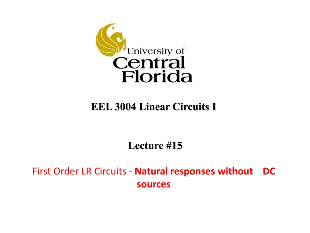
EEL 3004 Linear Circuits I Lecture #15 First Order LR Circuits - Natural responses without DC sources
Lecture Objectives The lecture today will focus on: Introduction to switching RL circuits Natural response of RL Circuits without DC sources Examples
RLC circuits with DC sources and NO Switching (Steady-state) If the circuit consists only of direct current and voltage sources (dc), and the switch has been closed or opened for long time, then the capacitor behaves as an open circuit, and the inductor behaves as a short circuit. Under DC conditions the circuit has been undisturbed for a long time
Natural Response RL circuits The natural response for an RL circuits are obtained when the external independent source is set to zero or removed as shown below. For the natural responses to exist it is required that the inductor have energy stored in it at the moment of switching and the equivalent RL circuits are obtained. This circuit will responds naturally due to its L &R equivalent values. After certain action (switching): We call it natural response or transient response. R s and L s Only No External source Our goal to find the voltages, currents and power after t > 0.
Natural Response of LR circuits IMPORTANT DEFINITIONS ?? ??????: For t < 0, we let ??0 = ???????? ??????? ???? ?????? ? = 0 For t > 0, we let ??0+= ???????? ??????? ???? ????? ? = 0 Therefore, for the inductor has these conditions met all the time: ??0+= ??0 = ??0
General Natural Response of LR circuits Any given resistive-capacitive circuit without external independent DC sources that can be reduced to a series equivalent L/R circuit. The general solution for iL(t) is given, ?? ??? = ??(0)? ? ? is the circuit time constant ? = ??(0)= ??(0 ) is the initial inductor value across in L.
General Natural Response of LR circuits Any given resistive-capacitive circuit without external independent DC sources that can be reduced to a series equivalent L/R circuit. The general solution for iL(t) is given, ?? ??? = ??(0)? ? ? is the circuit time constant ? = R: The total resistance seen by the inductor ??(0)= ??0 = ??0+ is the initial inductor value across in L. Simplified circuit
Natural Response of RL circuits The natural response for an RL circuit is analogous to the natural response of an RC circuit Consider the circuit where the switch moves from position a to b . =?
Natural Response of RL circuits The initial inductor current for t = 0- right before the switch is moved from a to b , is given by, Since the inductor current doesn t change its value instantaneously Applying KVL around the parallel RL circuit, An ordinary first-order differential equation with constant coefficients
Natural Response of RL circuits It can be easily shown that the general natural response of iL(t) is given by, Where iL(0) = Iois the initial inductor current, and the time constant,
Natural Response of RL circuits The voltage across the resistor is given by, The instantaneous power delivered to R, And the energy dissipated in R,
Natural Response of RL circuits The plot for the natural response of an RL circuit,
Example Initially the switch has been in position a for a long time. At t = 0, the switch is moved to position b . Determine the currents iL(t) and iR3(t) and voltage vR3 for t>0. Variable Values Unit Io Ro R1 R2 R3 L 2 A 2 8 5 4 0.5 H
The solution approach: The key is to find the for ??? after the switch is closed, i.e. for ??? ? 0. Once we solve for ??? then all the currents, voltages, power and energy can be expressed in terms of ??? . The inductor current ??? is known as state variable
Solution Use the General Formula The general solution (natural response) for iL(t) for t > 0: ?? ??? = ??(0+)? Where, ??(0+) is the initial inductor current ?? ? is the time constant given by ? ? = ?? ?? is the equivalent resistance seen by the inductor
Solution Use the General Formula (1) Need to find ??(0+) For t < 0 the inductor acts like a short circuit, Applying KCL at the top node yields, ?1= 0 ????? ?? ?? ? ????? ?? ? ? ?????? Hence, ?? ??? = ??(0+)? Since the current in the inductance doesn t change instantaneously, ??0 = ??0+= ??= 2 ?
(2) Need to find ? For t > 0, the equivalent circuit is shown below Simplified equivalent circuit, where So, by inspection the time constant is: ? =0.5 4.2= 0.12 ? Therefore, the general solution: ? = ??? ??= 2? ?0.12 ? ??? = ??0+?
Example Initially the switch has been in position a for a long time. At t = 0, the switch is moved to position b . Determine for t > 0 the currents iL(t) and iR3(t) and voltage vR3, Variable Values Unit Vo Io Ro R1 R2 R3 L 24 V 6 A 2 8 5 4 0.5 H
Solution Use the General Formula For t < 0, we use the circuit to find ??0 Use any analysis method to solve for??0 For t<0.
Solution Use the General Formula For t < 0 the inductor acts like a short circuit, Applying source transformation,
Assign v across all parallel branches Applying KCL to the single-node circuit yields, It can be seen that, Solving for iL(0) yields, ??0 = 2?6 + 24 = 3.6 ? 2 + 8 Since the current in the inductance doesn t change instantaneously, ??0+= ??0 = 3.6 ?
For t > 0, we use the circuit to find ?: finding the Thevenin total resistance seen by the inductor, RTh is given by, ? 0.5? 10.2 = 48.9 ?? ? = = ???
The current in R3 is given by, + ??3 - The voltage across R3 is given by,

