Understanding PLC Relay Logic Circuits for Control Systems
Explore the basic concepts of PLC relay logic circuits in control systems. Follow along with detailed diagrams and explanations by Mohd Haffiz Zainal Abidin, an electrical lecturer, to grasp the fundamentals of 24VDC control circuits with start and stop push buttons, contactors, and buzzers.
Uploaded on | 1 Views
Download Presentation

Please find below an Image/Link to download the presentation.
The content on the website is provided AS IS for your information and personal use only. It may not be sold, licensed, or shared on other websites without obtaining consent from the author. If you encounter any issues during the download, it is possible that the publisher has removed the file from their server.
You are allowed to download the files provided on this website for personal or commercial use, subject to the condition that they are used lawfully. All files are the property of their respective owners.
The content on the website is provided AS IS for your information and personal use only. It may not be sold, licensed, or shared on other websites without obtaining consent from the author.
E N D
Presentation Transcript
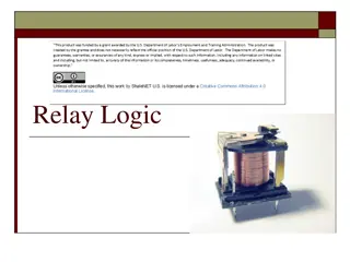
PLC Programmable Logic Control Relay Logic Circuit : Basic Concept By Mohd Haffiz Zainal Abidin College Community Electrical Lecturer
CONTROL CIRCUIT 24 VDC 0 VDC START PB K1 STOP PB L2 BLK L1 RED A2 A1 CR K1-NO K1-NO BUZZER
CONTROL CIRCUIT 24 VDC 0 VDC START PB K1 STOP PB L2 BLK L1 RED A2 A1 CR K1-NO K1-NO BUZZER
CONTROL CIRCUIT 24 VDC 0 VDC START PB K1 STOP PB L2 BLK L1 RED A2 A1 CR K1-NO K1-NO BUZZER
CONTROL CIRCUIT 24 VDC 0 VDC START PB K1 STOP PB L2 BLK L1 RED A2 A1 CR K1-NO K1-NO BUZZER
CONTROL CIRCUIT 24 VDC 0 VDC START PB K1 STOP PB L2 BLK L1 RED A2 A1 CR K1-NO K1-NO BUZZER
CONTROL CIRCUIT 24 VDC 0 VDC START PB K1 STOP PB L2 BLK L1 RED A2 A1 CR K1-NO K1-NO BUZZER
CONTROL CIRCUIT 24 VDC 0 VDC START PB K1 STOP PB L2 BLK L1 RED A2 A1 CR K1-NO K1-NO BUZZER
CONTROL CIRCUIT 24 VDC 0 VDC START PB K1 STOP PB L2 BLK L1 RED A2 A1 CR K1-NO K1-NO BUZZER
CONTROL CIRCUIT 24 VDC 0 VDC START PB K1 STOP PB L2 BLK L1 RED A2 A1 CR K1-NO K1-NO BUZZER
CONTROL CIRCUIT 24 VDC 0 VDC START PB K1 STOP PB L2 BLK L1 RED A2 A1 CR K1-NO HOLDING CIRCUIT K1-NO BUZZER
CONTROL CIRCUIT 24 VDC 0 VDC START PB K1 STOP PB L2 BLK L1 RED A2 A1 CR K1-NO HOLDING CIRCUIT K1-NO BUZZER
CONTROL CIRCUIT 24 VDC 0 VDC START PB K1 STOP PB L2 BLK L1 RED A2 A1 CR K1-NO K1-NO BUZZER
CONTROL CIRCUIT 24 VDC 0 VDC START PB K1 STOP PB L2 BLK L1 RED A2 A1 CR K1-NO K1-NO BUZZER

