Understanding Series Circuits in Electricity
Explore the basics of series circuits in electricity, including components, charge flow, current calculations, potential difference, and more. Learn how to calculate charge passing through a circuit, determine charge transfer time, and calculate current based on charge flow. Delve into the concept of potential difference as the driving force in a series circuit. Visualize the analogy of water flow with electrical charge and current to grasp these fundamental concepts effectively.

Download Presentation

Please find below an Image/Link to download the presentation.
The content on the website is provided AS IS for your information and personal use only. It may not be sold, licensed, or shared on other websites without obtaining consent from the author. If you encounter any issues during the download, it is possible that the publisher has removed the file from their server.
You are allowed to download the files provided on this website for personal or commercial use, subject to the condition that they are used lawfully. All files are the property of their respective owners.
The content on the website is provided AS IS for your information and personal use only. It may not be sold, licensed, or shared on other websites without obtaining consent from the author.
E N D
Presentation Transcript
This list shows some of the components that you will come across in your study of circuits at GCSE. You should try to memorise these, some are quite obvious (such as Ammeter, Voltmeter) but others are less obvious (such as Diode or LDR). Note the distinction between Cell and Battery , the longer line of the two is the positive terminal and the shorter is the negative terminal.
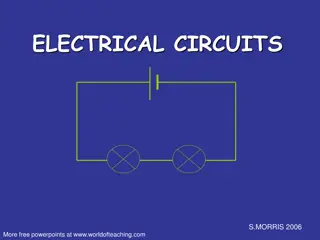
This is called a series circuit because the different components are connected in a line end to end between the positive and negative terminals of the cell or battery. Any break in the circuit at any point will cause the whole thing to stop working. When the switch is closed, electrons will flow from the cell, through the ammeter, through the filament bulb and back to the cell. Convention states that current flows from positive to negative but electrons do in fact flow from negative to positive. The flow rate of electrons in the circuit is measured in Amperes or Amps .It is usually abbreviated to A The flow volume of electrons in the circuit indicates the movement of Electrical Charge which is measured in Coulomb , usually abbreviated to C
Think of the Water in the river as the CHARGE Think of the Water Flow in the river as the CURRENT The FASTER the FLOW (Higher Current) the greater the amount of Water passing between the arrows Let Q be the amount of Water (Charge) Let I be the Water Flow Rate (Current) Let t be the length of the flow, in Seconds
Q. In a particular electrical circuit, 25 A flowed in 10 seconds, what was the charge in Coulombs passing through the circuit? Q. A battery charger is connected to a battery/cell and passes a current of 8 A. If the overall charge transferred to the battery/cell is 75,000 C, how long was the charger switched on for? Q. A circuit passes 400C of charge in 25 seconds, what is the current in the circuit?
This SERIES CIRCUIT has a 12V power supply, in scientific terms we would say that: The POTENTIAL DIFFERENCE in the circuit is 12 VOLTS It is the POTENTIAL DIFFERENCE that provides the Driving Force (Electromotive Force, E.M.F.) to push the current around the circuit. GREATER POTENTIAL DIFFERENCE GREATER DRIVING FORCE The Potential Difference is SHARED across EACH component in the circuit, so the more components you add in series, the lower the PD will be for each of them. In the example shown, there is only one component (the filament bulb) so it will feel the FULL PD of 12V (we disregard the ammeter, and the voltmeter is connected in parallel).
Q. What would be the PD across each of the filament bulbs if they were identical? A. PD is shared equally if they were identical, so the answer is 6V. If the components are not identical, the share of PD for each will vary. However, all of the PD is shared so that the sum total across each component equals the value of the source PD:
CURRENT IN SERIES CIRCUITS In series circuits, the value of the current flowing through ALL components is the SAME, and EQUAL to the current flow in ALL parts of the circuit. The ammeter here shows 2A flowing around the circuit, so the current passing through EACH filament lamp is 2A
RESISTANCE IN SERIES CIRCUITS In a series circuit the total resistance is the sum of all of the resistances of the individual components making up the circuit. This is fairly straightforward, and we measure the resistance of a circuit from OHMS LAW:
RESISTANCE IN SERIES CIRCUITS Take a look at this circuit. Each resistor shown is identical to the other. The CIRCUIT resistance is 6 OHM (6 ) and we can see this in 2 ways: The CIRCUIT resistance is 6 OHM (6 ) and we can see this in 2 ways: The sum of the resistances comes to 6 ohms) Using Ohms Law we have 12V / 2A = 6 )