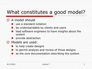
Learn how UML activity diagrams portray the sequence of actions, workflow, and decision paths in a structured format. Explore the various elements like actions, control flow, decision nodes, objects flow, and more that aid in representing complex processes effectively.
Please find below an Image/Link to download the presentation.
The content on the website is provided AS IS for your information and personal use only. It may not be sold, licensed, or shared on other websites without obtaining consent from the author. If you encounter any issues during the download, it is possible that the publisher has removed the file from their server.
You are allowed to download the files provided on this website for personal or commercial use, subject to the condition that they are used lawfully. All files are the property of their respective owners.
The content on the website is provided AS IS for your information and personal use only. It may not be sold, licensed, or shared on other websites without obtaining consent from the author.
E N D
Presentation Transcript
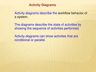
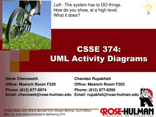
UML ACTIVITY DIAGRAMS In UML an activity diagram is used to display the sequence of actions They show the workflow from start to finish Detail the many decision paths that exist in the progression of events contained in the activity Very useful when parallel processing may occur in the execution of some activities
UML ACTIVITY DIAGRAMS An example of an activity diagram is shown below (We will come back to that diagram)
ACTIVITY An activity is the specification of a parameterized sequence of behavior Shown as a round-cornered rectangle enclosing all the actions and control flows
ACTIONS AND CONSTRAINS An action represents a single step within an activity Constraints can be attached to actions
CONTROL FLOW Shows the flow of control from one action to the next Its notation is a line with an arrowhead. Initial Node Final Node, two types: Activity Final Node Flow Final Node
OBJECTS FLOW An object flow is a path along which objects or data can pass An object is shown as a rectangle A short hand for the above notation
DECISION AND MERGE NODES Decision nodes and merge nodes have the same notation: a diamond shape The control flows coming away from a decision node will have guard conditions
FORK AND JOIN NODES Forks and joins have the same notation: either a horizontal or vertical bar They indicate the start and end of concurrent threads of control Join synchronizes two inflows and produces a single outflow The outflow from a join cannot execute until all inflows have been received
PARTITION Shown as horizontal or vertical swim lane Represents a group of actions that have some common characteristic
MORE ON ACTIVITY DIAGRAMS Interruptible Activity Regions Expansion Regions Exception Handlers
INTERRUPTIBLE ACTIVITY REGION Surrounds a group of actions that can be interrupted Example below: Process Order action will execute until completion, when it will pass control to the Close Order action, unless a Cancel Request interrupt is received, which will pass control to the Cancel Order action.
EXPANSION REGION An expansion region is an activity region that executes multiple times to consume all elements of an input collection Example of books checkout at a library modeled using an expansion region: Checkout Books Place Books in Bags Find Books to Borrow Checkout Book Show Due Date
EXPANSION REGION Another example: Encoding Video Encode Video Save Encoded Video Extract Audio from Frame Encode Video Frame Attach Audio to Frame Capture Video
EXCEPTION HANDLERS An exception handler is an element that specifies what to execute in case the specified exception occurs during the execution of the protected node In Java Try block corresponds to Protected Node Catch block corresponds to the Handler Body Node