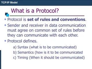
Universal Host Identifiers in TCP/IP
The traditional Internet addressing scheme introduced with IPv4 and the transition to IPv6, how TCP/IP defines hosts, and the importance of universal communication service and host identification within internetworking. Explore the virtual structure of the internet and the unique integer addressing method used in TCP/IP for network communication.

Download Presentation

Please find below an Image/Link to download the presentation.
The content on the website is provided AS IS for your information and personal use only. It may not be sold, licensed, or shared on other websites without obtaining consent from the author.If you encounter any issues during the download, it is possible that the publisher has removed the file from their server.
You are allowed to download the files provided on this website for personal or commercial use, subject to the condition that they are used lawfully. All files are the property of their respective owners.
The content on the website is provided AS IS for your information and personal use only. It may not be sold, licensed, or shared on other websites without obtaining consent from the author.
E N D
Presentation Transcript
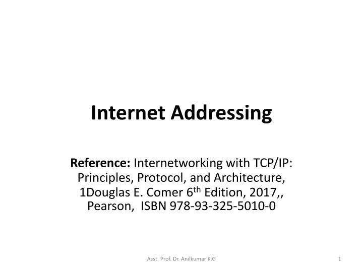
Internet Addressing Reference: Internetworking with TCP/IP: Principles, Protocol, and Architecture, 1Douglas E. Comer 6thEdition, 2017,, Pearson, ISBN 978-93-325-5010-0 Asst. Prof. Dr. Anilkumar K.G 1
Introduction The traditional Internet addressing scheme, which was introduced with version 4 of the Internet Protocol (called as IPv4), and is widely used. The next version is IPv6 (version 6 of the Internet Protocol). 2 Asst. Prof. Dr. Anilkumar K.G
Universal Host Identifiers TCP/IP uses the term host to refer to an end system that attaches to the internet. A host can be a large powerful general purpose computer. A host may have an interface that humans use (screen, keyboard, etc) or a network printer. A host can use wired or wireless network technology. The Internet divides all machines into two classes: Routers and Hosts Any device that is not a router is classified as a host. 3 Asst. Prof. Dr. Anilkumar K.G
Universal Host Identifiers A communication system is said to supply universal communication service if the system allows an attached host to communicate with any other attached host. To make a communication system universal, it needs a globally accepted method of identifying each host that attached to it. The identifiers are classified as names, addresses, and routes: A name identifies what an object is, An address identifies where it is, and A route tells how to get there. 4 Asst. Prof. Dr. Anilkumar K.G
Universal Host Identifiers Names, addresses and routes refer to lower level representations of host identifiers, Unlike other types of networks, an internet is a virtual structure, imagined by its designers, and implemented by layered protocol SW running on both hosts and routers. Because the Internet is virtual, its designers are free to choose packet formats and sizes, addresses, delivery techniques, and so on. There is nothing is dedicated by HW. 5 Asst. Prof. Dr. Anilkumar K.G
Universal Host Identifiers The designers of TCP/IP chose an addressing scheme in which each host on an Internet is assigned a unique integer address called its Internet Protocol address (known as, IP address). An IP address is divided into two parts: A prefix of the address identifies the network to which the host attaches and A suffix of the address identifies a specific host on the network. All hosts attached to the same network share a common prefix. 6 Asst. Prof. Dr. Anilkumar K.G
Universal Host Identifiers An IP address is a number identifying a user computer or another device on the Internet It is similar to a mailing address, which identifies where postal mail comes from and where it should be delivered. IP addresses uniquely identify the source and destination of data transmitted with the Internet Protocol. 7 Asst. Prof. Dr. Anilkumar K.G
IPv4 and IPv6 Addressing Scheme IPv4 addresses are 32 bits long (four octets). An example of an IPv4 address is 216.58.216.164. The maximum number of IPv4 addresses, which is called its address space, is about 4.3 billion (232, or 4,294,967,296). A major advantage of IPv6 is that it uses 128 bits of data to store an address, permitting 2128unique addresses, or the size of its address space is 340 duodecillion. Is much larger than IPv4. 8 Asst. Prof. Dr. Anilkumar K.G
IPv4 and IPv6 Addressing Scheme The designers also decided to make IP addresses fixed size (32-bit for IPv4 and 128-bit for IPv6). Decisions are made to use fixed-size IP addresses and divide each address into a network ID (netId) and a host ID (hostId). Each address is a pair <netId (prefix), hostId (suffix)> where netId identifies a network and hostId identifies a host on that network. Allocating many bits to the prefix allows Internet to contain many networks. Allocating many bits to a suffix means a network with many hosts, limits the number of networks in internet. 9 Asst. Prof. Dr. Anilkumar K.G
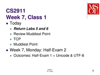
IPv4 Classful Addressing Scheme To accommodate into various network systems, the IP address designers did not choose a single division of the address instead: invented a classful addressing scheme that allowed a given network to be large, medium, or small classes. Figure 5.1 illustrates how the original classful addressing scheme divided each IPv4 address into two parts. Although most of classful addressing scheme is no longer in usage, but it explains how the IPv4 multicast address space was chosen. 10 Asst. Prof. Dr. Anilkumar K.G
IPv4 Classful Addressing Scheme 11 Asst. Prof. Dr. Anilkumar K.G
IPv4 Classful Addressing Scheme Courtesy : https://www.ittsystems.com/introduction-to-subnetting/ 12 Asst. Prof. Dr. Anilkumar K.G
Courtesy : Wikipedia 13 Asst. Prof. Dr. Anilkumar K.G
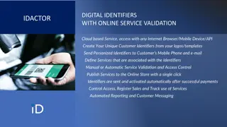
IPv4 Classful Addressing Scheme Bit-wise representation of IPv4 classful addresses: In the following bit-wise representation, n indicates a bit used for the network ID. H indicates a bit used for the host ID. X indicates a bit without a specified purpose. The number of addresses usable for hosts in each network is always (2N 2), where N is the number of host field bits, and the subtraction of 2 adjusts for the use of the all-bits-zero host portion for network address and the all-bits-one host portion as a broadcast address. 14 Asst. Prof. Dr. Anilkumar K.G
Courtesy : Wikipedia 15 Asst. Prof. Dr. Anilkumar K.G
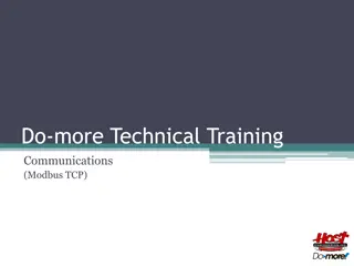
IPV4 Classful Addressing Scheme Courtesy : https://learningnetwork.cisco.com/docs/DOC-12872 16 Asst. Prof. Dr. Anilkumar K.G
IPv4 Classful Addressing Scheme The address range of Class A network is actually 1-126 because 0.x.x.x and 127.x.x.x are reserved. With these classes, a computer/device can look at the first three bits of any IP address and determine what class it belongs to. For example, the 192.168.1.250 IP address falls into the Class C range (192 = 110000002) Looking at the Host ID portion of the classes, we can determine how many hosts (or number of individual IP addresses) a network in each class will support. For example, a Class C network will ideally support up to 256 host IDs i.e. from 00000000 (decimal 0) to 11111111 (decimal 255). 17 Asst. Prof. Dr. Anilkumar K.G
IPv4 Classful Addressing Scheme Two of these host addresses (00000000 and 11111111) in Class C cannot be assigned to hosts because all 0s represents the network address while all 1s represents the broadcast address. This leaves with 254 (28-2) host IDs. A simple formula calculates the number of hosts supported by a network is: No. of usable IP addresses (host addresses) = 2host_bits 2 Anyone who needed a network that supports up to 254 hosts can use a Class C network. What if you only need just 10 IP addresses? You still get a Class C network. This wastage of IP addresses It is even worse for Class B (65,534 usable IP addresses per network) and Class A (16,777,214 usable IP addresses per network)! 18 Asst. Prof. Dr. Anilkumar K.G
IPv4 Classful Addressing Scheme In the classful addressing scheme, each address is said to be self-identifying because the boundary between prefix and suffix can be computed from the address alone Class A addresses used for networks with large hosts (it has 7- bit networkID and 24-bit hostID). Class B addresses used for medium size networks (it allocates 14 bits to the networkID and 16 bits to the hostID). Class C addresses used for networks that have less than 28(256) hosts (it allocates 21 bits to the networkID and 8 bits to hostID). 19 Asst. Prof. Dr. Anilkumar K.G
Dotted Decimal Address with IPv4 IPv4 addresses are written as four decimal integers separated by decimal points. A 32-bit binary IP address can be given as 10000000 00001010 00000010 00011110 and is written as dotted decimal integers 128.10.2.30 (a Class B address) Application programs such as a web browser allow a user to enter a dotted decimal value instead of a computer name. 20 Asst. Prof. Dr. Anilkumar K.G
IPv4 Subnet Addressing How can the technology accommodate growth without abandoning the original classful addressing scheme? A technique called subnet addressing or subnetting allows a single network prefix to be used for multiple physical networks. To understand subnetting, it is important to think about individual sites connected to the Internet. A subnet is a logical partition of an IP network into multiple, smaller network segments. Subnetting is typically used to subdivide large networks into smaller, more efficient sub-networks. 21 Asst. Prof. Dr. Anilkumar K.G
IPv4 Subnet Addressing For example, a university started with a single LAN and obtained an IPv4 prefix (networkID). If the university adds another LAN, the original addressing scheme would require the university to obtain a second networkID for the second LAN. Suppose the university has only a few computers. It can assign host addresses and arrange internal forwarding . That is a site can choose and use IPv4 addresses in unusual ways internally as long as all hosts and routers within the site agree to honor the site s addressing scheme. Other sites on the Internet can treat addresses as standard addresses with a network prefix that belongs to the site. Subnet addressing takes advantage of the freedom by allowing a site to divide the host portion of their addresses among multiple networks. 22 Asst. Prof. Dr. Anilkumar K.G
IPv4 Subnet Addressing How subnet addressing works? Suppose a site has been assigned a single class B prefix, 128.10.0.0 (it has 16-bit networkID and 16-bit hostID). The rest of the Internet assumes each address at the site has one physical network with the 16-bit networkID (128.10). If the site obtains a second physical network, the site can use subnet addressing by using a portion of the hostID field(0.0) to identify which physical network to use. Only hosts and routers at the site will know that there are multiple physical networks and how to forward traffic among them. Figure 5.3 shows an example using the third octet (3rd8-bit of the addresses) of each address to identify a subnet. 23 Asst. Prof. Dr. Anilkumar K.G
IPv4 Subnet Addressing 24 Asst. Prof. Dr. Anilkumar K.G
IPv4 Subnet Addressing In the Figure 5.3, shows how the subnetting possible on a network with Class B address, 128.10.0.0 : All hosts on the Network1 (net-address: 128.10.1 .0) have IP addresses of the form: 128.10.1. Two hosts with IP addresses 128.10.1.1 and 128.10.1.2. Similarly, hosts on Network2 (net-address: 128.10.2 .0) have IP addresses of the form: 128.10.2. Two hosts with IP addresses 128.10.2.1 and 128.10.2.2. If R receives a packet, it checks the destination address: If the address starts with 128.10.1, the R delivers the packet to a host on Network1. If the address starts with 128.10.2, the R delivers the packet to a host on Network2. 25 Asst. Prof. Dr. Anilkumar K.G
IPv4 Subnet Addressing Instead of dividing the 32-bit IPv4 address into a network prefix and host suffix, subnetting divides the IPv4 address into an internet portion and a local portion The internet portion remains the same as for networks that do not use subnetting. When using subnet addressing, a 32-bit IPv4 address as having an internet portion and a local portion; where the internet portion identifies a site, possibly with multiple physical networks, and the local portion identifies a physical network and host at that site (see Figure 5.3). Figure 5.4 illustrates how the example divides the IPv4 address for subnetting. 26 Asst. Prof. Dr. Anilkumar K.G
IPv4 Subnet Addressing 27 Asst. Prof. Dr. Anilkumar K.G
IPv4 Subnet Addressing Routers throughout the Internet use the top level of the hierarchy to forward a packet to the correct site: Once the packet enters the site, local routers use the physical network octet to select the correct network. Hence the packet reaches the correct network, a router uses the host portion to identify a particular host (see Figure 5.3). 28 Asst. Prof. Dr. Anilkumar K.G
Fixed Length IPv4 Subnets In the example in Figure 5.3 shows a site was assigned a 16-bit network prefix and used the third octet of the address to identify a physical network at the site and the fourth octet for the host on that network. The TCP/IP standard for subnet addressing recognizes that not every site will have a 16-bit prefix and not every site needs same addressing hierarchy. Figure 5.3 represents a site that only has two physical networks. Imagine a company that owns 20 large buildings and has deployed 20 LANs in each building. Suppose the site has a single 16-bit network prefix and it wants to use subnetting for all its local networks. 29 Asst. Prof. Dr. Anilkumar K.G
Fixed Length IPv4 Subnets How should the 16-bit local (host) portion of the address be divided into fields for a physical network and host? ANS: The 16-bit local portion of Class B address is shown in Figure 5.4(b) It has an 8-bit physical network identifier and 8-bit host identifier. Using 8-bit to identify a physical network means a manager can generate up to 256 unique physical network IDs (LAN IDs). Similarly, with 8-bit host portion, a manager can generate up to 256 host IDs for each network. Unfortunately, the company has 400 (20 x 20) local networks, which exceeds the 254 (28-2) possible numbers. 30 Asst. Prof. Dr. Anilkumar K.G
Fixed Length IPv4 Subnets To permit flexibility, the subnet standard does not specify that a site must always use the third octet to specify a physical network in a Class-B address system as per the Figure 5.4(b). Instead a site can choose how many bits of the local portion to dedicate to the physical network, and how many to dedicate to the host. The example company with 400 networks might choose the division that Figure 5.5 illustrates because a 10-bit field allows up to 1024 local networks . 31 Asst. Prof. Dr. Anilkumar K.G
Fixed Length IPv4 Subnets The example company with 400 networks might choose the division that Figure 5.5 illustrates because a 10-bit field allows up to 1024 networks (LANs). 32 Asst. Prof. Dr. Anilkumar K.G
Fixed Length IPv4 Subnets The idea of allowing a site to choose a division for the local portion of its address and then using the division throughout the site is known as fixed-length subnetting. Fixed-length subnetting is easy to understand because it partitions the local portion of an address between networks and hosts (see Figure 5.4). A manager chooses how many networks the site can have, and also determine the maximum number of hosts on each network. Figure 5.6 illustrates the possible choices if a site uses fixed-length subnetting with a 16-bit local portion. 33 Asst. Prof. Dr. Anilkumar K.G
Fixed Length IPv4 Subnets 34 Asst. Prof. Dr. Anilkumar K.G
Fixed Length IPv4 Subnets As the Figure 5.6 illustrates, an organization that adopts fixed-length subnetting must choose a compromise: If the organization opts for a large no. of physical networks, none of the networks can contain many hosts; If the organization expects to connect many hosts to a network, the number of physical network must be small. For example, allocating 3 bits to identify a physical network result in up to 6 networks that each support up to 8190 hosts. Allocating 12 bits results in up to 4094 networks, but restricts the size of each to 14 hosts. 35 Asst. Prof. Dr. Anilkumar K.G
Fixed Length IPv4 Subnets It should be clear why the designers did not choose a specific division for subnetting. No single portion of the local part of the address works for all organizations: Some need many networks with few hosts/network, while others need a few networks with many hosts attached to each. Sits do not all receive a 16-bit local portion, so the subnetting standard handles cases where a site is dividing fewer bits. 36 Asst. Prof. Dr. Anilkumar K.G
Variable Length IPv4 Subnet Most sites use fixed-length subnetting because it is straight forward to understand and administer. When the designers invented subnetting, they have realized that fixed-length subnetting would not suffices for all sites. The standard specifies that an organization can select a subnet partition on a per network basis and is called variable-length subnetting: Once a partition has been selected for a particular network, the partition never changes. All hosts and routers attached to that network must follow the decision; if they do not, datagram can be lost or misrouted. 37 Asst. Prof. Dr. Anilkumar K.G
Implementation of IPv4 Subnets with Masks The subnet technology makes configuration of either fixed or variable length subnets. The standard specifies that a 32-bit mask is used to specify the subnet division. Thus a site using subnet addressing must choose a 32- bit subnet mask for each network. The mask covers the Internet portion and the physical network part (of the local portion) of the address: Bits in the subnet mask are set to 1 if machines on the network treat the corresponding bit in the IP address as part of the subnet prefix, and 0 if they treat the bit as part of the host identifier. 38 Asst. Prof. Dr. Anilkumar K.G
Implementation of IPv4 Subnets with Masks Example: consider the following 32-bit subnet mask: 11111111 11111111 11111111 00000000 specifies that the first 3 octets identify the network and the fourth octet identifies a host network. Corresponds to the portion that Figure 5.5 illustrates where the physical network portion occupies 10 bits. 11111111 11111111 11111111 11000000 An interesting twist in subnet addressing is that the original standard did not restrict subnet masks to select contiguous bits of the address. 39 Asst. Prof. Dr. Anilkumar K.G
Implementation of IPv4 Subnets with Masks For example, a network might be assigned the mask: 11111111 11111111 00011000 01000000 which selects the first two octets, 2 bits from the 3rd octet, and 1 bit from the 4thoctet. Although the standard allows one to arrange address like above; this makes the network management almost impossible! Therefore, it is recommended that sites only use contiguous subnet masks. 40 Asst. Prof. Dr. Anilkumar K.G
IPv4 Subnet Mask Representation and Slash Notation Specifying subnet masks in binary is both awkward and prone to errors. Hence SW allows alternative masking representation: Most SW allows managers to use dotted decimal representation when specifying IPv4 subnet masks. Dotted decimal works well if a site can align the subnet boundary on octet boundaries. The example Figure 5.4(b) shows how easy it is to understand subnetting when the 3rdoctet of an address is used to identify a physical network and the 4thoctet is used to identify a host. 41 Asst. Prof. Dr. Anilkumar K.G
IPv4 Subnet Mask Representation and Slash Notation Instead of binary, the subnet mask has a dotted decimal representation: 11111111 11111111 11111111 00000000 = 255 . 255 . 255 . 0 Subnet addresses and masks represented in braces as a 3-tuple: {<network number>, <subnet number>, <host number>} In this representation, each section can be represented in dotted decimal, and the value -1 means all ones . For example, if the subnet mask of a class C network is 255.255.255.0, it can be written as {-1, -1, -1, 0}. 42 Asst. Prof. Dr. Anilkumar K.G
IPv4 Subnet Mask Representation and Slash Notation The main advantage is that it abstracts away from details of bit fields and emphasizes the values as three parts of the address. The disadvantage is that it does not accurately specify how many bits are used for each part of the address: For example, {128.10, -1, 0} denotes an address with a network number 128.10, all ones(-1) in the subnet field and all zeros in the host field. The address could correspond to a subnet where the boundary occurs after the 3rdoctet or could correspond to a situation like one in Figure 5.5 Where the boundary allocates 10 bits to the network and 6 bits to the host. 43 Asst. Prof. Dr. Anilkumar K.G
The Classless IPv4 Addressing Scheme What is classless addressing? In place of the three classes addressing schemes (Class A, Class B, and Class C), a new addressing scheme extends the idea used in subnet addressing to permit a network prefix to be an arbitrary length (not fixed) is called classless addressing. The designers modified forwarding and route propagation techniques to handle classless addresses. As a result the entire Internet technology has become known as Classless Inter-Domain Routing (CIDR). 44 Asst. Prof. Dr. Anilkumar K.G
The Classless IPv4 Addressing Scheme To understand the impact of CIDR in networking, one needs to know 3 facts: 1. The classful scheme did not divide network addresses into equal size classes. 2. Because class C prefixes only suffice for small networks and are not amenable to subnetting, demand for class C prefixes was much smaller than demand for class B prefixes. 3. Studies showed that at the rate class B numbers were being assigned, class B prefixes would be exhausted quickly. 45 Asst. Prof. Dr. Anilkumar K.G
The Classless IPv4 Addressing Scheme: Supernetting One of the first uses of classless addressing was known as supernetting: To understand how supernetting works, consider a medium- sized organization that join the Internet. Under classful addressing scheme, such an organization would request a class B prefix. The supernetting scheme allows an ISP to assign the organization a block of class C addresses instead of a single class B number. The block must be large enough to number all the networks in the organization and must lie on a boundary that is a power of 2. 46 Asst. Prof. Dr. Anilkumar K.G
The Classless IPv4 Addressing Scheme: Supernetting For example, suppose the organization expects to have 200 networks: Supernetting can assign the organization a block of 256 contiguous Class C numbers. Although the first intended use of CIDR involved blocks of class C addresses, the designers realized that CIDR could be applied in a much broader context: They envisioned a hierarchical addressing model in which each commercial ISP could be given a large block of internet addresses that the ISP could then allocate to subscribers. 47 Asst. Prof. Dr. Anilkumar K.G
The Classless IPv4 Addressing Scheme Like subnet addressing, CIDR uses a 32-bit addressing mask to specify the boundary between prefix and suffix. Contiguous I bits in the mask specify the size of the prefix, and 0 bits in the mask correspond to the suffix. At first glance, a CIDR mask appears to be identical to a subnet mask. The major difference is that a CIDR mask is not merely known within a site. Instead, a CIDR mask specifies the size of a network prefix, and the prefix is known globally. 48 Asst. Prof. Dr. Anilkumar K.G
The Classless IPv4 Addressing Scheme For example, suppose an organization is assigned a block of 2048 (211)contiguous host addresses (IP addresses) starting at address 128.211.168.0. It includes last 3 bits of octet3 and whole bits of octet4 (total 11 bits) The following Figure 5.8 lists the binary values of addresses in the range: 49 Asst. Prof. Dr. Anilkumar K.G
The Classless IPv4 Addressing Scheme From the Figure 5.8, because of 2048 is 211, eleven bits are needed for the host portion of an address. Out of 2048 IP addresses, only 2046 (211 2)are used (host ID with all 0s and all 1s used for networking and broadcasting purposes). That means the CIDR address mask will have 21 bits set (the division between network prefix and host suffix occurs after the 21stbit). In Binary, the address mask is: 11111111 11111111 11111000 00000000 (/21 as per CIDR scheme) In decimal, the address mask is: 255.255.248.0 50 Asst. Prof. Dr. Anilkumar K.G