Using FX7400, FX7500, and FX9500 GPIO Connections for Control Systems
In this guide, learn about the GPIO connections of FX7400, FX7500, and FX9500 for control systems. Discover the pinouts and setups for typical configurations with light stacks and motion sensors. Understand the power requirements and connection details for operating these devices effectively. Explore the various input and output options available for integrating these systems into your projects.

Download Presentation

Please find below an Image/Link to download the presentation.
The content on the website is provided AS IS for your information and personal use only. It may not be sold, licensed, or shared on other websites without obtaining consent from the author.If you encounter any issues during the download, it is possible that the publisher has removed the file from their server.
You are allowed to download the files provided on this website for personal or commercial use, subject to the condition that they are used lawfully. All files are the property of their respective owners.
The content on the website is provided AS IS for your information and personal use only. It may not be sold, licensed, or shared on other websites without obtaining consent from the author.
E N D
Presentation Transcript
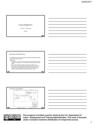
FX7400 GPIO Connections 1. Two optically isolated GP outputs (open drain to GND) 2. Two optically isolated GP inputs (5V logic level pulled high) 3. +24V DC available when operating from AC power GPIO CONNECTOR PINOUTS 1 2 3 4 5 6 7 +24V O/P #1 O/P #2 GND I/P #1 I/P #2 GND
FX7400 - Typical setup with light stack and motion sensors (AC power) +24V DOUT1 DOUT2 GND DIN1 DIN2 GND Motion sensors may also be powered from +24V pin if sensors support 24V DC operation and total current drain is less than 1 Amp. VIN GND + + NC LAMP LAMP NO Note: NC signifies Normally Closed contact on relay. NO identifies Normally Open contact on relay. MOTION SENSOR 2 VIN GND NC Note: Lamps can be 24V incandescent or LEDs with suitable current limiting for 24V operation. LEDs require a common anode (positive) connection. NO MOTION SENSOR 1
FX7400 - Typical setup with light stack and motion sensors (PoE operation) +24V DOUT1 DOUT2 GND DIN1 DIN2 GND VIN GND + + NC LAMP LAMP NO Note: NC signifies Normally Closed contact on relay. NO identifies Normally Open contact on relay. MOTION SENSOR 2 VIN GND NC V+ V- Note: DC power supplies in the range 5V to 24V may be suitable provided that they are compatible with light stack and sensor power requirements. NO DC Power Supply MOTION SENSOR 1
FX9500 GPIO Connections 1. Four GP outputs (open collector to GND, 0.1 Amp max) 2. Four optically isolated GP inputs (external supply required) GPIO CONNECTOR PINOUTS 1 2 3 4 5 6 7 8 9 10 11 12 DIN1/ DIN2 REF DIN3/ DIN4 REF DIN1 DIN2 DIN3 DIN4 GND DOUT1 DOUT2 DOUT3 DOUT4 GND
FX9500 - Typical setup with light stack and motion sensors DIN1/ DIN2 REF DIN3/ DIN4 REF DIN1 DIN2 DIN3 DIN4 GND DOUT1 DOUT2 DOUT3 DOUT4 GND VIN GND + LAMP V+ NC NO DC MOTION SENSOR 2 + LAMP Power Supply VIN GND NC + LAMP V- NO Note: NC signifies Normally Closed contact on relay. NO identifies Normally Open contact on relay. MOTION SENSOR 1 Note: DC power supplies in the range 5V to 24V may be suitable provided that they are compatible with light stack and sensor power requirements.
FX7500 GPIO Connections +24V DOUT1 DOUT2 DOUT3 GND DIN1 DIN2 GND Pin # 1 2 3 4 5 6 7 8 Pin Name +24V DC Power GP output #1 GP output #2 GP output #3 GND GP input #1 GP input #2 GND Direction O O O O - I I - Description Supplies +24V DC at up to 1 Amp Signal for GP output #1 Signal for GP output #2 Signal for GP output #3 Ground Connection Signal for GP input #1 Signal for GP input #2 Ground Connection
FX7500 - Typical setup with light stack and motion sensors (AC power) DOUT 1 DOUT 2 DOUT 3 +24V GND DIN1 DIN2 GND VIN GND + + + NC LAMP LAMP LAMP NO Note: NC signifies Normally Closed contact on relay. NO identifies Normally Open contact on relay. MOTION SENSOR 2 VIN GND Motion sensors may also be powered from +24V pin if sensors support 24V DC operation and total current drain is less than 1 Amp. NC Note: Lamps can be 24V incandescent or LEDs with suitable current limiting for 24V operation. LEDs require a common anode (positive) connection. NO MOTION SENSOR 1
FX7500 - Typical setup with light stack and motion sensors (PoE operation) +24V DOUT1 DOUT2 DOUT3 GND DIN1 DIN2 GND + + + VIN GND NC LAMP LAMP LAMP NO MOTION SENSOR 2 VIN GND NC V+ V- Note: DC power supplies in the range 5V to 24V may be suitable provided that they are compatible with light stack and sensor power requirements. NO DC Power Supply Note: NC signifies Normally Closed contact on relay. NO identifies Normally Open contact on relay. MOTION SENSOR 1