UWB Sensing Methods and KPIs in IEEE 802.15 WPANs
Explore UWB sensing methods and KPIs in the context of the IEEE P802.15 Working Group for Wireless Personal Area Networks (WPANs). The document discusses the applications of Ultra-Wideband (UWB) technology for presence detection, environment mapping, and high-throughput data use cases. It covers topics such as interference mitigation, coexistence improvement, enhanced ranging capabilities, and low-latency streaming. Contributions from Huawei Technologies offer insights into safeguarding high-throughput data use cases, reducing complexity, and improving interoperability within the WPAN framework.

Download Presentation

Please find below an Image/Link to download the presentation.
The content on the website is provided AS IS for your information and personal use only. It may not be sold, licensed, or shared on other websites without obtaining consent from the author. If you encounter any issues during the download, it is possible that the publisher has removed the file from their server.
You are allowed to download the files provided on this website for personal or commercial use, subject to the condition that they are used lawfully. All files are the property of their respective owners.
The content on the website is provided AS IS for your information and personal use only. It may not be sold, licensed, or shared on other websites without obtaining consent from the author.
E N D
Presentation Transcript
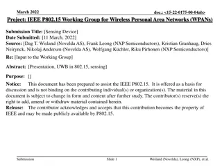
Sep 2021 Project: IEEE P802.15 Working Group for Wireless Personal Area Networks (WPANs) doc.: <15-21-XXXX> Submission Title: [UWB sensing methods and KPIs in 802.15] Date Submitted: [] Source: [Xiaohui Peng, David Xun Yang, Ziyang Guo, Stephen McCann] Company [Huawei Technologies] Re: [Input to the Working Group] Abstract: [Presentation, UWB in 802.15, sensing] Purpose: [] Notice: discussion and is not binding on the contributing individual(s) or organization(s). The material in this document is subject to change in form and content after further study. The contributor(s) reserve(s) the right to add, amend or withdraw material contained herein. Release: The contributor acknowledges and accepts that this contribution becomes the property of IEEE and may be made publicly available by P802.15. This document has been prepared to assist the IEEE P802.15. It is offered as a basis for Submission Slide 1 Xiaohui Peng, Huawei
July 2021 doc.: <15-21-XXXX> PAR Objective Proposed Solution (how addressed) Safeguards so that the high throughput data use cases will not cause significant disruption to low duty-cycle ranging use cases Interference mitigation techniques to support higher density and higher traffic use cases Other coexistence improvement Backward compatibility with enhanced ranging capable devices (ERDEVs) Improved link budget and/or reduced air-time Additional channels and operating frequencies Improvements to accuracy / precision / reliability and interoperability for high-integrity ranging Reduced complexity and power consumption Hybrid operation with narrowband signaling to assist UWB Enhanced native discovery and connection setup mechanisms Sensing capabilities to support presence detection and environment mapping RSS method, Doppler method, ranging method, DOA method, joint method, reflection method, real antenna array method, virtual antenna array method Low-power low-latency streaming Higher data-rate streaming allowing at least 50 Mbit/s of throughput Support for peer-to-peer, peer-to-multi-peer, and station-to- infrastructure protocols Infrastructure synchronization mechanisms Submission Slide 2 Xiaohui Peng, Huawei
July 2021 doc.: <15-21-XXXX> Presence detection using UWB Submission Slide 3 Xiaohui Peng, Huawei
July 2021 doc.: <15-21-XXXX> Presence detection Presence detection detects the position change of an object with respect to time or its reference point, which is typically described by displacement, direction, velocity or acceleration. The purpose of presence detection using an UWB device or UWB network is to Identify the presence of a target Determine the number of targets Identify the type of target Monitor the vital sign Recognize the gesture Detect a moving target Measure the range of device-free targets in a given environment [2]. Presence detection can be applied to many scenarios including [2] Smart home, e.g., light and air condition control Security, e.g., intrusion detection in pre-defined areas Health care, e.g., fall detection of the elderly and children Game control, e.g., gesture control for VR game Submission Slide 4 Xiaohui Peng, Huawei
July 2021 doc.: <15-21-XXXX> Presence detection RSS method RSS variation: The presence of an object (e.g., human and robot) will lead to RSS (Received Signal Strength) variations, especially when the LOS (line of sight) path is blocked by a moving target. Operation mode Using a pair of links, only the presence of a target can be detected Using a UWB network, both the presence and the activity area can be detected RSS information can be extracted from CIRs (channel impulse response) Node1 Node3 Human blocks the LOS path between node2 and node3 presence Node2 Submission Slide 5 Xiaohui Peng, Huawei
July 2021 doc.: <15-21-XXXX> Presence detection KPIs of RSS method (Note: The material below builds upon the definitions presented in [1].) Receiver Sensitivity: The minimum power level at which the receiving node is able to detect the transmitted signal. E.g., -70dBm is a requirement that the received signal strength should be larger than -70dBm. Range Coverage: The maximum allowable distance from a sensing device to the target within which the SNR is above a pre-defined threshold. E.g., <5m@13dB indicates that the maximum allowable distance from a sensing device to the target with a 13dB SNR threshold is 5 meters. Field of View (FOV): The coverage area of a sensing device in terms of angle. E.g., 50 is a requirement that the coverage area of a sensing device is 50 . Probability of Detection: The ratio of the number of correct predictions to the number of all aimed samples in terms of gestures/activities/motions. E.g., >95% is a requirement that the percentage of correct detections is greater than 95%. Submission Slide 6 Xiaohui Peng, Huawei
July 2021 doc.: <15-21-XXXX> Presence detection Doppler method Doppler information: UWB sensors can be used to measure the Doppler effect caused by a moving target. Doppler effect is mainly determined by The operation frequency The target speed relative to the sensor The RCS (Radar Cross Section) of the measured target Operation mode Mono-static mode: this mode contains only one sensor, and can only detect the radial speed of a target Multi-static mode: this mode contains multiple spatially diverse sensors, and can detect the absolute velocity of a target Transmitting signal Reflected signal Node Mono-static mode Multi-static mode Node2 Node1 Submission Slide 7 Xiaohui Peng, Huawei
July 2021 doc.: <15-21-XXXX> Presence detection KPIs of Doppler method (Note: The material below builds upon the definitions presented in [1].) Velocity Resolution: The minimum radial velocity difference required for a sensing device to distinguish between two targets moving in the same range. E.g., 0.1m/s indicates that two targets are distinguishable if their velocity difference is greater than 0.1m/s. Velocity Accuracy: The difference between the estimated velocity and the actual velocity of a target. E.g., 0.2m/s is a requirement that the difference between the estimated velocity and the actual velocity is less than 0.2m/s. Range Coverage: The maximum allowable distance from a sensing device to the target within which the SNR is above a pre-defined threshold. E.g., < 5m@13dB indicates that the maximum allowable distance from a sensing device to the target with a 13dB SNR threshold is 5 meters. Field of View (FOV): The coverage area of a sensing device in terms of angle. E.g., 50 is a requirement that the coverage area of a sensing device is 50 . Probability of Detection: The ratio of the number of correct predictions to the number of all aimed samples in terms of gestures/activities/motions. E.g., >95% is a requirement that the percentage of correct detections is greater than 95%. Submission Slide 8 Xiaohui Peng, Huawei
July 2021 doc.: <15-21-XXXX> Presence detection Ranging method Range information: UWB sensors can be used to measure the propagation distance of the signal reflected by a target. Ranging performance is mainly determined by The bandwidth ( 500MHz) The SNR (Signal to Noise Ratio) The RCS (Radar Cross Section) of the measured target Operation mode Mono-static mode: this mode contains only one sensor, and can be used to measure the two-way propagation delay from the sensor to the target Multi-static mode: this mode contains multiple spatially diverse sensors, and can be used to measure the location of the target Transmitting signal Reflected signal Node Node2 Node1 Mono-static mode Multi-static mode Submission Slide 9 Xiaohui Peng, Huawei
July 2021 doc.: <15-21-XXXX> Presence detection KPIs of ranging method (Note: The material below builds upon the definitions presented in [1].) Range Resolution: The minimum range difference required for a sensing device to distinguish between two targets in the same direction. E.g., 50cm indicates that two targets are distinguishable if their range difference is greater than 50cm. Range Accuracy: The difference between the estimated range and the actual range of a target. E.g., 10cm is a requirement that the difference between the estimated range and the actual range is less than 10cm. Range Coverage: The maximum allowable distance from a sensing device to the target within which the SNR is above a pre-defined threshold. E.g., < 5m@13dB indicates that the maximum allowable distance from a sensing device to the target with a 13dB SNR threshold is 5 meters. Field of View (FOV): The coverage area of a sensing device in terms of angle. E.g., 50 is a requirement that the coverage area of a sensing device is 50 . Probability of Detection: The ratio of the number of correct predictions to the number of all aimed samples in terms of gestures/activities/motions. E.g., >95% is a requirement that the percentage of correct detections is greater than 95%. Submission Slide 10 Xiaohui Peng, Huawei
July 2021 doc.: <15-21-XXXX> Presence detection DOA method Angle information: An UWB sensor with multiple antennas can be used to measure the DOA (direction of arrival) of a target. DOA performance is mainly determined by The antenna array aperture The operation frequency The SNR (Signal to Noise Ratio) The RCS (Radar Cross Section) of the measured target Operation mode Mono-static mode: this mode contains only one sensor with multiple antennas Multi-static mode: this mode contains multiple spatially diverse sensors and each sensor has multiple antennas Processor Processor TX TX and RX RX Multi-static mode Mono-static mode Submission Slide 11 Xiaohui Peng, Huawei
July 2021 doc.: <15-21-XXXX> Presence detection KPIs of DOA method (Note: The material below builds upon the definitions presented in [1].) Angular Resolution (Horizontal / Vertical): The minimum angle difference required for a sensing device to distinguish between two targets in the same range. E.g., 10 indicates that two targets are distinguishable if their angle difference is greater than 10 . Angular Accuracy (Horizontal / Vertical): The difference between the estimated angle and the actual angle of an object. E.g., 1 is a requirement that the difference between the estimated angle and the actual angle of an object is less than 1 . Range Coverage: The maximum allowable distance from a sensing device to the target within which the SNR is above a pre-defined threshold. E.g., < 5m@13dB indicates that the maximum allowable distance from a sensing device to the target with a 13dB SNR threshold is 5 meters. Field of View (FOV): The coverage area of a sensing device in terms of angle. E.g., 50 is a requirement that the coverage area of a sensing device is 50 . Probability of Detection: The ratio of the number of correct predictions to the number of all aimed samples in terms of gesture/activities/motions. E.g., >95% is a requirement that the percentage of correct detections is greater than 95%. Submission Slide 12 Xiaohui Peng, Huawei
July 2021 doc.: <15-21-XXXX> Presence detection joint method Doppler+Range Target radial velocity SNR (Signal to Noise Ratio) Operation frequency and bandwidth ( 500MHz) RCS (Radar Cross Section) of the measured target Doppler+Angle Target radial velocity Operation frequency SNR (Signal to Noise Ratio) Antenna array aperture RCS (Radar Cross Section) of the measured target Angle+Range Antenna array aperture Bandwidth ( 500MHz) SNR (Signal to Noise Ratio) RCS (Radar Cross Section) of the measured target Angle+Range+Doppler Antenna array aperture Operation frequency and Bandwidth ( 500MHz) SNR (Signal to Noise Ratio) Target radial velocity RCS (Radar Cross Section) of the measured target Submission Slide 13 Xiaohui Peng, Huawei
July 2021 doc.: <15-21-XXXX> Presence detection summary of KPIs The proposed KPIs can be grouped into 4 different categories Coverage Resolution Accuracy Other performance Method Probability of detection (%) Receiver sensitivity (dBm) Range (m) FOV ( ) Range (m) Angle ( ) Velocity (m/s) Range (m) Angle ( ) Velocity (m/s) NA NA NA NA NA NA RSS method Doppler method NA NA NA NA NA Ranging method NA NA NA NA NA NA NA NA NA NA DOA method NA Joint method Submission Slide 14 Xiaohui Peng, Huawei
July 2021 doc.: <15-21-XXXX> Environment mapping using UWB Submission Slide 15 Xiaohui Peng, Huawei
July 2021 doc.: <15-21-XXXX> Environment mapping The purpose of environment mapping using a UWB device or UWB network is to Identify the environment (e.g., determine whether the environment is a living room, a meeting room or another environment) Determine the rough structure of the environment Reconstruct a two-dimensional map of the environment Reconstruct a three-dimensional map of the environment Environment mapping can be applied to many scenarios including Smart home, e.g., indoor robot navigation Security, e.g., environment structure identification for fire rescue Game control, e.g., digital map construction for virtual reality games Submission Slide 16 Xiaohui Peng, Huawei
July 2021 doc.: <15-21-XXXX> Environment mapping Reflection method The principles behind environment mapping using a reflection method are as follows: First, a UWB sensor is mounted on a platform that can move along at least two orthogonal directions of the building Second, determine the locations of all the walls. A UWB sensor radiates a signal and receives the signal reflected by the wall to infer the position of the scatter point Third, determine the start and end points of all the walls Last, determine how the different walls are connected Mapping performance is mainly determined by The bandwidth The SNR (Signal to Noise Ratio) The dynamic range,which is defined as the ratio between the maximum and the minimum intensity of the image. The imaging accuracy is limited by the accuracy of UWB sensor position Submission Slide 17 Xiaohui Peng, Huawei
July 2021 Environment mapping KPIs of reflection method Coverage/footprint: The maximum imaging area covered by an antenna beam within which the SNR is above a pre-defined threshold. E.g., < 5m2@13dB indicates that the maximum ranging area of an antenna beam with a 13dB SNR threshold is 5 square meters. Spatial Resolution: The ability to distinguish between two targets in an image, which is defined by the half power beam width (HPBW). E.g., 50cm indicates that two targets are distinguishable when the spatial difference between them is greater than 50cm. Reconstruction accuracy: The accuracy of the reconstructed map to the ground truth map. E.g., 2 indicates that the root mean square error (RMSE) between the reconstructed map and the ground truth map is 2. Radiometric resolution: Radiometric quality per pixel, defined as ? = 10lg distributed target intensity values. E.g., -10dB indicates that a pixel intensity change larger than -10dB can be detected from the image. doc.: <15-21-XXXX> ? ?+ 1 , with ? being the mean and ? the standard deviation of the Submission Slide 18 Xiaohui Peng, Huawei
July 2021 doc.: <15-21-XXXX> Environment mapping Real antenna array method The principles behind environment mapping using a real antenna array are as follows: First, some UWB nodes with antenna arrays are deployed in the environment Second, determine the locations of all the walls. A UWB sensor radiates a signal and receives the signal reflected by the wall using multiple antennas to infer the range and the angle of the scatter point Third, determine the start and end points of all the walls Last, determine how different walls are connected Mapping performance is mainly determined by The bandwidth The SNR (Signal to Noise Ratio) The dynamic range,which is defined as the ratio between the maximum and the minimum intensity of the image. The antenna array aperture The operation frequency Submission Slide 19 Xiaohui Peng, Huawei
July 2021 doc.: <15-21-XXXX> Environment mapping KPIs of real antenna array method 1/2 Coverage/footprint: The maximum imaging area covered by a real antenna beam within which the SNR is above a pre-defined threshold. E.g., < 5m2@13dB indicates that the maximum imaging area of a real antenna beam with a 13dB SNR threshold is 5 square meters. Spatial Resolution: The ability to distinguish between two targets in an image, which is defined by half power beam width (HPBW). E.g., 50cm indicates that two targets are distinguishable when the spatial difference between them is greater than 50cm. Integrated side lobe ratio (ISLR) : The ratio of the total power in all of the side lobes to the power in the main lobe. E.g., -13dB indicates that the ratio of the total power in all of the side lobes to the power in the main lobe of a point target is -13dB. Peak side lobe ratio (PSLR): The ratio of the peak intensity of the most prominent side lobe to the peak intensity of the main lobe. E.g., -13dB indicates that the ratio of the peak intensity of the most prominent side lobe to the peak intensity of the main lobe of a point target is -13dB. Submission Slide 20 Xiaohui Peng, Huawei
July 2021 doc.: <15-21-XXXX> Environment mapping KPIs of real antenna array method 2/2 Reconstruction accuracy: The accuracy of the reconstructed map to the ground truth map. E.g., 2 indicates that the root mean square error (RMSE) between the reconstructed map and the ground truth map is 2. Radiometric resolution Radiometric quality per pixel, defined as ? = 10lg distributed target intensity values. E.g., -10dB indicates that a pixel intensity change larger than -10dB can be detected from the image. ? ?+ 1 , with ? being the mean and ? the standard deviation of the Submission Slide 21 Xiaohui Peng, Huawei
July 2021 Environment mapping Virtual antenna array method The principles behind environment mapping using an virtual antenna array are as follows: First, a UWB sensor is mounted on a moving platform working as a SAR (synthetic aperture radar), which uses the motion of the radar antenna over a target region to provide finer spatial resolution than a conventional stationary real aperture radar Second, determine the locations of all the walls. A UWB sensor radiates a signal and receives the signal reflected by the wall with a moving antenna to infer the position of the scatter point Third, determine the start and end points of all the walls Last, determine how different walls are connected doc.: <15-21-XXXX> Mapping performance is mainly determined by The bandwidth The SNR (Signal to Noise Ratio) The dynamic range,which is defined as the ratio between the maximum and the minimum intensity of the image. The virtual antenna aperture The operation frequency It requires accurate sensor position and motion compensation Submission Slide 22 Xiaohui Peng, Huawei
July 2021 Environment mapping KPIs of Virtual antenna array method 1/2 Coverage/footprint: The maximum imaging area covered by a virtual antenna beam within which the SNR is above a pre-defined threshold. E.g., < 5m2@13dB indicates that the maximum imaging area of a virtual antenna beam with a 13dB SNR threshold is 5 square meters. Spatial Resolution: The ability to distinguish between two targets in an image, which is defined by half power beam width (HPBW). E.g., 50cm indicates that two targets are distinguishable when the spatial difference between them is greater than 50cm. Integrated side lobe ratio (ISLR) : The ratio of the total power in all of the side lobes to the power in the main lobe. E.g., -13dB indicates that the ratio of the total power in all of the side lobes to the power in the main lobe of a point target is -13dB. Peak side lobe ratio (PSLR): The ratio of the peak intensity of the most prominent side lobe to the peak intensity of the main lobe. E.g., -13dB indicates that the ratio of the peak intensity of the most prominent side lobe to the peak intensity of the main lobe of a point target is -13dB. doc.: <15-21-XXXX> Submission Slide 23 Xiaohui Peng, Huawei
July 2021 Environment mapping KPIs of Virtual antenna array method 2/2 Reconstruction accuracy: The accuracy of the reconstructed map to the ground truth map. E.g., 2 indicates that the root mean square error (RMSE) between the reconstructed map and the ground truth map is 2. Radiometric resolution Radiometric quality per pixel, defined as ? = 10lg distributed target intensity values. E.g., -10dB indicates that a pixel intensity change larger than -10dB can be detected from the image. doc.: <15-21-XXXX> ? ?+ 1 , with ? being the mean and ? the standard deviation of the Submission Slide 24 Xiaohui Peng, Huawei
doc.: <15-21-XXXX> Environment mapping KPI Summary Resolution Other performance Reconstruction accuracy Method Coverage Spatial resolution (m) Radiometric resolution ( ) ISLR PSLR NA NA Reflection method Real antenna array method Virtual antenna array method Submission Xiaohui Peng, Huawei
doc.: <15-21-XXXX> References 1. Usage model terminology for WLAN Sensing, IEEE 802.11-20/0905r2. 2. Presence and proximity detection using WLAN Sensing, IEEE 802.11- 19/1772r0. Submission Xiaohui Peng, Huawei