Vertical Thermal Conductance Test for Carrier Boards in Production Design
"Explore the significance of thermal impedance in operating temperatures for SCROD and upper carrier boards. Follow a detailed test setup involving heat loads and temperature measurements, aiming to assess thermal performance accurately."

Download Presentation

Please find below an Image/Link to download the presentation.
The content on the website is provided AS IS for your information and personal use only. It may not be sold, licensed, or shared on other websites without obtaining consent from the author. If you encounter any issues during the download, it is possible that the publisher has removed the file from their server.
You are allowed to download the files provided on this website for personal or commercial use, subject to the condition that they are used lawfully. All files are the property of their respective owners.
The content on the website is provided AS IS for your information and personal use only. It may not be sold, licensed, or shared on other websites without obtaining consent from the author.
E N D
Presentation Transcript
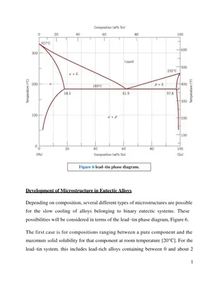
Vertical thermal conductance test for carrier rev E In the production design, thermal impedance of the sidewalls through carrier boards is a potentially very significant term in operating temperature for the SCROD and upper carrier boards. FOR EXAMPLE Board Load total W Sidewall width m length m height m 0.00175 0.01225 material P above W dT deg C Temperature on top deg C 64.1 62.5 SCROD 18.2 2.00E-05 1.309913 0.007 copper copper 18.2 18.2 1.6 0.5 0.087 carrier 17.8 2.00E-05 1.309913 0.007 0.00175 0.00725 copper copper 36 36 3.2 0.6 62.0 58.9 0.087 carrier 17.8 2.00E-05 1.309913 0.007 0.00175 0.00725 copper copper 53.8 53.8 4.7 0.8 58.3 53.6 0.087 carrier 17.8 2.00E-05 1.309913 0.007 0.00175 0.00725 copper copper 71.6 71.6 6.3 1.1 52.8 46.5 0.087 carrier 17.8 2.00E-05 1.309913 0.007 0.00175 0.00541 copper copper 89.4 89.4 7.8 1.0 45.4 37.5 0.087 HVB 5 0.0073 0.075 0.0098 7075 94.4 6.5 36.5 COLD PLATE 30 IN THE EXAMPLE Vias of present design pattern, IPC wall spec 45 Watts flows down each side through bottom carrier board [Pessimistic?? Hopefully!] Results in nominal 8 degree rise crossing vertically through bottom carrier board At SCROD, sidewalls at 64 degrees and this is optimistic (no interface impedance!) At the SCROD, 22 degree rise relative to infinitely thermally conducting carrier boards TEST IT
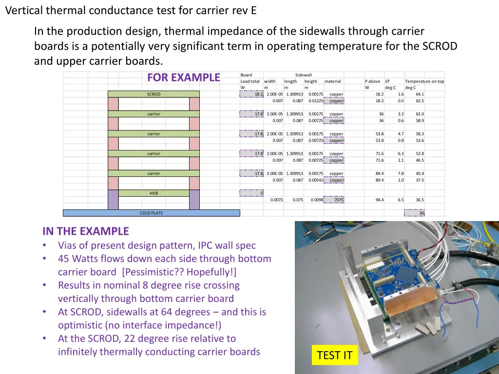
All 16 screws carefully torqued to 12 inch pounds! Load: 3x TIP31C, VCE=10 V, total IC=4.0 A, soldered to copper plate inserted into sidewall stack, with thermal goop on copper plate only SCROD standing in for carrier rev E Two spacers below (needed for clearance) Temperature measured with contact thermocouple with small beads of thermal goop at outside of spacer blocks immediately above/below the SCROD. And above/below the junction to HVB bracket and at bottom of HVB bracket, and top of cold plate nearby. Cold plate with water ~0 C (measured in reservoir)
With 40 W (one-side) load as detailed on previous slide, temperatures in C Result is ~17 C rise vertically through the board Location All dry HVB bottom gooped HVB top also gooped Spacer above board 49.3 46.8 tbd, will update slides Spacer below board 32.5 31.1 Spacer above HVB 25.0 21.9 HVB near top 18.9 16.8 HVB near bottom 13.5 10.0 Cold plate nearby 7.3 7.5 Note: there is of course some variation in the exact position & quality of thermal contact at the different measurement points.
By the way, this is an old HVB that has been hacked to be compatible with new and old bolt pattern. Certainly sacrificing some cooling performance! We really should be doing this test with new, alodined HVB brackets and the new- type cold plate. Don t have that yet for the test fixture (another topic ).
UPDATE 12/12/2014 First reconfirmed ~same results as before Then, switched to real carrier rev E, and relocated the heater slightly (it should be in next carrier board position for more accurate results, but wasn t possible using the SCROD as a stand-in; also the SCROD couldn t be put in place of bottom carrier board (connector conflicts with HVB bracket)). Now, real carrier board, in bottom position, ~40W heater in next carrier board position.
Omega # 88008E 1 3 mm2 surface probe
With 41.9 W (one-side) load (10.04V, 4.17A), all screws unlubricated, torqued to 12 inch-pounds (pardon my units!). Temperatures in C Result (dry) is ~14 C rise vertically through the board [wet ~7 C] Location Carrier Dry Carrier w/ thermal grease Spacer above board 36.7 28.5 Spacer below board 22.4 21.6 Spacer above HVB 19.4 19.0 HVB near top 16.6 16.3 HVB near bottom 10.1 10.2 Cold plate nearby 7.0 6.6


 load as detailed on previous slide,")


 load (10.04V, 4.17A),")