Waveguide Transmission Line Model for TE10 Mode Analysis
Explore the development of a transmission line model for the TE10 waveguide mode, examining transverse equivalent networks and field equations with introduced voltage and characteristic impedance. Gain insight into the modal amplitudes and wave impedance for waveguide structures.
Download Presentation

Please find below an Image/Link to download the presentation.
The content on the website is provided AS IS for your information and personal use only. It may not be sold, licensed, or shared on other websites without obtaining consent from the author. If you encounter any issues during the download, it is possible that the publisher has removed the file from their server.
You are allowed to download the files provided on this website for personal or commercial use, subject to the condition that they are used lawfully. All files are the property of their respective owners.
The content on the website is provided AS IS for your information and personal use only. It may not be sold, licensed, or shared on other websites without obtaining consent from the author.
E N D
Presentation Transcript
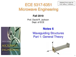
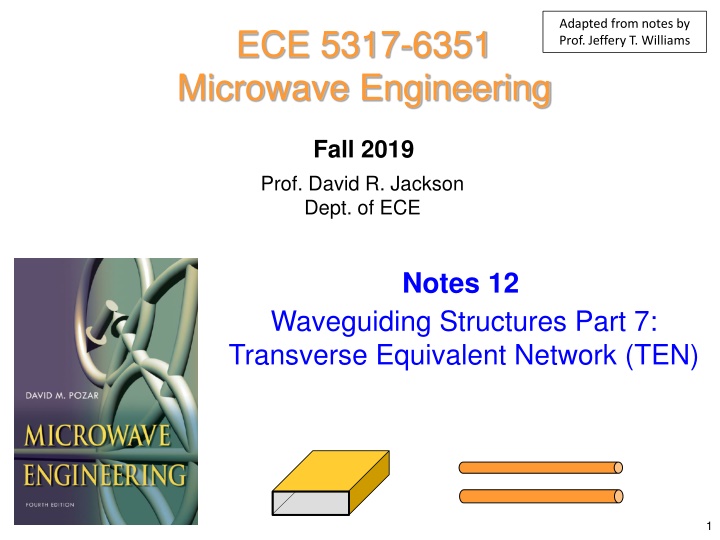
Adapted from notes by Prof. Jeffery T. Williams ECE 5317-6351 Microwave Engineering Fall 2019 Prof. David R. Jackson Dept. of ECE Notes 12 Waveguiding Structures Part 7: Transverse Equivalent Network (TEN) 1
Waveguide Transmission Line Model Our goal is to come up with a transmission line model for a waveguide mode. y b The waveguide mode is not a TEM mode, but it can be modeled as a wave on a transmission line. x a z I + -V z Transverse Equivalent Network model of TE10 waveguide mode 2
Waveguide Transmission Line Model (cont.) For a waveguide mode, voltage and current are not uniquely defined. y y TE10 Mode A b - ( ) x x E b y a V + x z a B = jk z 10sin E E x e z y a B b ( ) ( ) = = E dr = = = jk z jk z , , sin sin V x z V x z E dy E b x e V x e z z 10 0 AB y a a 0 A ( ) = The voltage depends on x! / 2,0 V E b V a 0 10 3
Waveguide Transmission Line Model (cont.) Examine the transverse (x, y) fields of a waveguide mode: Modal amplitudes ( ( ) + + = + jk z jk z ( , , ) E x y z ( , ) e x y A e A e z z t t ) + + = jk z jk z ( , , ) H x y z ( , ) h x y A e A e z z t t 1 Note: = z ( , ) h x y ( ) e The shape function et (x,y) has an arbitrary amplitude normalization. t t Z w Note: The minus sign above arises from: 1 = = z E Z Z Z ( ) H or w TE TM t t Z w k = Z Z z TM TE k c z Wave impedance 4
Waveguide Transmission Line Model (cont.) Introduce a defined voltage into the field equations: V C A 0 1 We may use whatever definition of voltage we wish here. (In other words, C1 is arbitrary.) We then have: 1 C ( ) + + = + jk z jk z ( , , ) E x y z ( , ) x y e V e V e z z 0 0 t t 1 1 C ( ) + + = jk z jk z ( , , ) H x y z ( , ) x y h V e V e z z 0 0 t t 1 5
Waveguide Transmission Line Model (cont.) Next, introduce a characteristic impedance (having an arbitrary value) into the equations: + Z C V Z V Z + = jk z jk z 0 0 0 ( , , ) H x y z ( , ) h x y e e z z t t 1 0 0 + 1 V Z V Z e + = jk z jk z ( , , ) H x y z ( , ) h x y 0 0 e z z t t C 2 0 0 where C Z 1 C 2 0 6
Waveguide Transmission Line Model (cont.) Summary of Fields ( ) V z 1 C ( ) + + = + jk z jk z ( , , ) E x y z ( , ) e x y V e V e z z 0 0 t t 1 ( ) I z + V Z V Z 1 + = jk z jk z ( , , ) H x y z ( , ) h x y 0 0 e e z z t t C 2 0 0 The z dependence of the transverse fields behaves like voltage and current on a transmission line. 7
Waveguide Transmission Line Model (cont.) The transmission-line model is called the Transverse Equivalent Network (TEN) model of the waveguide. ( ) I z TEN ( ) + - V z z 0, Z k z E H V I t same kz t Waveguide 8
Waveguide Transmission Line Model (cont.) Power flow down the waveguide (complex power): 1 2 ( ) ( ) z S = WG * zdS P E H t t 1 2 1 ( ) ( ) ( ) z S = * * t zdS ( , ) e x y ( , ) x y V z I h t * 2 C C 1 1 ( ) ( ) z ( ) z S = WG TEN * t zdS ( , ) e x y ( , ) h x y P P t * 2 C C 1 Complex power flowing down the TEN transmission line. 9
Waveguide Transmission Line Model (cont.) Assume we choose to have: ( ) z ( ) z = WG TEN P P Then we have the following constraint: ( ) S = * 2 * t zdS ( , ) e x y ( , ) h x y C C 1 t It is not necessary to make this assumption of equal powers, but it is a useful choice that can be made (we will adopt this choice). 10
Waveguide Transmission Line Model (cont.) Summary of Constants (assuming equal powers) C C = 1 Z 0 2 ( ) S = * 2 * t z dS ( , ) e x y ( , ) h x y C C 1 t Once we pick Z0, the constants are determined. = Z Z The most common choice: 0 w 11
Waveguide Transmission Line Model (cont.) Summary ( ) V z 1 C ( ) + + = + jk z jk z ( , , ) E x y z ( , ) e x y V e V e z z 0 0 t t 1 ( ) I z + V Z V Z 1 + = jk z jk z ( , , ) H x y z ( , ) h x y 0 0 e e z z t t C 2 0 0 C C ( ) = = 1 Z Z Z most common choice 0 0 w 2 ( ) S = * 2 * t z dS ( , ) e x y ( , ) h x y C C Z 1 t TE k z k 1 = Z z = = Z Z Z z ( , ) h x y ( ) e TM or w TE TM t t Z c w 12
TE10 Mode of Rectangular Waveguide y We make the following choices: Choose Z0 = ZTE Assumepower equality b x a z C C = Z 0 = 1 Z TE 10 z k TE 2 ( ) S = * 2 * t z dS ( , ) e x y ( , ) h x y C C 2 1 t = 10 2 z k k a = k c 13
TE10 Mode (cont.) y Calculate this term: ( ) S = * 2 * t z dS ( , ) e x y ( , ) h x y C C 1 t b x a so z = sin y e x t 1 x a S = * 2 2 sin C C dS 1 * TE 1 Z a = x sin h x t Z a a b 1 x TE = 2 sin dydx = * TE Z Z a TE 10 z k 0 0 1 ab = * TE Note: 2 Z The transverse shape function et has been chosen (arbitrarily) to have a unit amplitude at the center of the waveguide. 14
TE10 Mode (cont.) y We have: 1 ab = * 2 C C 1 * TE 2 Z b C C x = Z 1 a TE 2 z Take the conjugate of the second one and then multiply the two equations together. ab = sin y e x 2 = C Solution: t a 1 2 1 = x sin h x ab t Z a = C TE Note: 1 2 The solution is unique to within a phase term (we choose the phase to be zero here). = Z TE 10 z k 1 ab = C 2 2 Z TE 15
TE10 Mode (cont.) Recall: ( ) V z 1 C ( ) ab + + = + jk z jk z = ( , , ) E x y z ( , ) e x y V e V e C z z 1 2 0 0 t t 1 1 ab ( ) I z = C 2 2 Z + V Z V Z 1 TE + = jk z jk z ( , , ) H x y z ( , ) h x y 0 0 e e z z t t C = sin y e x t 2 0 0 a 1 = x sin h x t Z a Hence: TE = Z TE 10 z k ( ) V z 2 ab ( ) + + = + jk z jk z y ( , , ) sin t E x y z x V e V e z z 0 0 a ( ) I z + 2 ab 1 V Z V Z + = jk z jk z x ( , , ) H x y z sin 0 0 Z x e e z z t TE Z a TE TE TE 16
TE10 Mode (cont.) y Summary for TE10 mode ab = 10 TE Z b = C 10 z k x 1 2 a 1 ab 2 = C = 10 2 z z k k 2 10 TE = 2 Z sin y e x a t a 1 = x sin h x t Z a TE = Z ( ) V z TE 10 z k 2 ( ) + + = + jk z jk z y ( , , ) sin t E x y z x V e V e z z 0 0 ab a ( ) I z + V Z V Z 2 ab + = jk z jk z x 0 0 ( , , ) H x y z sin x e e z z t a TE TE 17
Example: Waveguide Discontinuity For a 1 [V/m] (field at the center of the guide) incident TE10 mode in guide A, find the TE10 mode fields in both guides, and the reflected and transmitted powers. = jk z inc y sin E x e za a B y r = = 0 a b z A x z = 0 0 b a a 2 = = 2 0 158.0 rad / m k k = = 2.2856 cm 1.016 cm 2.54 10 GHz = a b za a 2 = = = 2 0 304.1 rad / m k k r zb r a f 18
Example (cont.) TEN = sin y e x t a TE TE 0, b Z k 0, a Z k zb za 1 = x sin h x t Z a 0 V+ TE TV+ 0 = Z 0 0 V+ TE 10 z k ab = C Convention: Choose Z0 = ZTE Assumepower equality 1 Note: 2 C1 is the same for both guides, but C2 is different. 1 ab = C 2 2 Z TE ( ) + = jk z inc t ( , , ) x y z ( , ) e x y E A e z t = = = a TE 499.7 Z Z ( ) += 1 ( , ) 0 a A e x y k since already has 1 [ ] V/m t za = = = b TE 259.6 Z Z ab 0 b k + + = = = V C A C zb 0 1 1 2 19
Example (cont.) TEN ( ) ( ) ( ) z + + = + jk z jk z V z V e e za za 0 a + = jk z V V Te TE zb TE 0, b Z k 0, a Z k 0 b zb za + V Z V T Z ( ) ( ) z + = jk z jk z 0 I e e za za 0 V+ TV+ a 0 + a 0 0 V+ ( ) z = jk z 0 I e zb b 0 b + Z Z Z Z = = 0.316 0 0 b a Equivalent reflection problem: 0 0 b a T = + = 1 0.684 TE a Z TE b Z 0 0 Note: The above TEN enforces the continuity of voltage and current at the junction, and hence the tangential electric and magnetic fields are automatically continuous in the WG problem. 20
Example (cont.) TEN Hence we have: ab ( ) ( ) z ( ) + = + jk z jk z 0.316 V e e za za TE TE 0, b Z k 0, a Z k a 2 zb za ab ( ) z ( ) = jk z 0.684 V e zb 0 V+ TV+ b 2 0 0 V+ 1 ab ( ) ( ) z ( ) + = jk z jk z 0.316 I e e za za a 2 Z 0 a ( ) 0.684 Z ab = sin y e x ( ) z = jk z I e zb t a = = 158.0 rad / m k b 2 za 0 b 1 304.1 rad / m k = x sin h x zb t Z a TE Recall that for the TE10 mode: = Z TE 10 z k 1 C ( ) = ( , , ) E x y z ( , ) e x y V z ab t t = C 1 1 1 2 ( ) z = ( , , ) x y z ( , ) h x H y I 1 ab t t = C C 2 2 2 Z TE 21
Example (cont.) y B r z Hence, for the waveguide problem we have the fields as: A x 0 z = 0 b a a 1 C ab ( ) ( ) + = + jk z jk z ( , , ) x y z ( , ) e x y 0.316 E e e za za ta t 2 1 1 1 ab ( ) ( ) + = 0.3 jk z jk z ( , , ) x y z ( , ) h x y 16 H e e za za t a t 2 C Z 2 0 a 1 C ab ( ) = j k z ( , , ) x y z ( , ) 0. 84 6 E e x y e zb t b t 2 1 1 1 ab ( ) = jk z ( , , ) x y z ( , ) h x y 0.684 H e zb tb t 2 C Z 2 0 b 22
Example (cont.) Substituting in for C1 and et, we have (guide A): 1 C ab ( ) ( ) + = + jk z jk z ( , , ) x y z ( , ) e x y 0.316 E e e za za ta t 2 1 1 ab ab ( ) ( ) + = + 0.316 jk z jk z y ( , , ) x y sin E z x e e za za t a 2 a 2 = sin y e x t a ab = C 1 1 2 = x sin h x t Z a 1 ab TE = C 2 = 2 Z Z TE TE 10 z k 23
Example (cont.) Substituting in for C2 and ht, we have (guide A): 1 1 ab ( ) ( ) + = 0.3 jk z jk z ( , , ) x y z ( , ) h x y 16 H e e za za t a t 2 C Z 2 0 a = TE a Z Z 0 a 1 1 T a 1 TE a a b ( ) ( ) + = jk z jk z x ( , , ) x y z sin 0.316 H x e e za za ta E 2 Z a Z 1 TE a a b 2 Z 24
Example (cont.) Substituting in for C1 and et, we have (guide B): 1 C ab ( ) = j k z ( , , ) x y z ( , ) 0. 84 6 E e x y e zb t b t 2 1 1 ab ab ( ) = jk z y ( , , ) x y z sin 0. 84 6 E x e zb tb 2 a 2 25
Example (cont.) Substituting in for C2 and ht, we have (guide B): 1 1 ab ( ) = jk z ( , , ) x y z ( , ) h x y 0.684 H e zb tb t 2 C Z 2 0 b = TE b Z Z 0 b 1 1 T b 1 T b ab ( ) = jk z x ( , , ) x y z sin 0.684 H x e zb tb E E 2 Z a Z 1 TE a b 2 Z b 26
Example (cont.) Summary of Fields ( ) ( ) + = + jk z jk z y ( , , ) x y z sin 0.316 E x e e za za ta a = = TE a 499.7 Z 1 TE a ( ) ( ) + = jk z jk z x ( , , ) x y z sin 0.316 H x e e za za ta TE b Z a 259.6 Z = = 158.0 rad / m k za ( ) 304.1 rad / m k = jk z y ( , , ) x y z sin 0.684 E x e zb zb tb a 1 TE b ( ) = jk z x ( , , ) x y z sin 0.684 H x e zb tb Z a 27
Example (cont.) Power Calculations: Note: In this example,Z0 and are real. ab ( ) 1 + + = = = Recall: V C A C C 0 1 1 1 2 2 1 2 1 2 1 1 2 1 TE a ab 2 + + + = = = * inc a Re Re P V I V 0 0 0 * 0 2 Z Z a 2 1 2 1 2 1 TE a ab 2 2 + + = = * ref a Re P V I 0 0 2 Z 2 ( ) ( ) 1 2 1 2 1 TE a ab 2 2 + + = = * trans b P Re 1 1 V I 0 0 2 Z 28
Example (cont.) Final Results: = = inc a 1.161 mW P B y r ref a 0.116 mW = P trans b P 1.045 mW z A x z = 0 0 b a = = 2.2856 cm 1.016 cm 2.54 10 GHz = a b a = Note: 90.1% of the incident power is transmitted. r f 29
Quarter-Wave Transformer in Waveguide A quarter-wave transformer is shown here. = Z Z Z Goal: 0 0 0 T a b , d Determine: T = / 4 d gT x = TE i Z Z Top view 0 i TE TE 10 10 r rT a Z Z Z 0T 0a 0b z d Now 100% of the incident power is now transmitted. 30
Quarter-Wave Transformer in Waveguide (cont.) Waveguide problem x Top view TE TE 10 10 r rT a Z Z Z 0T 0a 0b z d TEN 0, T Z k Z Z 0a zT 0b d 31
Quarter-Wave Transformer in Waveguide (cont.) Design recipe: x Top view TE TE = 1 ) : Z Z Z Z Determine 10 10 r 0 0 0 0 T T a b rT a Z Z Z 0T = 0a 2 ) : / 0b k Z k Determine z 0 0 zT T zT d 2 = 2 T 3 ) : k k k Determine T zT a = Z Z Z 0 0 0 T a b = 4 ) : k k Determine 0 rT T rT = / 4 d gT = : k 5) Determine T T zT = 2 / 6 ) : Determine gT gT T 0, T Z Z k Z 0a zT 0b = : / 4 d d 7) Determine d gT 32
Quarter-Wave Transformer in Waveguide (cont.) Example: = = Results: 2.2856 cm 1.016 cm 2.54 10 GHz = a b = 1.53 0.716 cm rT = = d r f x Top view TE TE 10 10 r rT a Z Z Z 0T 0a 0b z d 33
Matching Elements in Waveguide Note: Rectangular Waveguide (end view) Planar discontinuities are modeled as purely shunt elements. Inductive iris Capacitive iris Resonant iris The equivalent circuit gives us the correct reflection and transmission of the TE10 mode. 34
Matching Elements in Waveguide (cont.) Inductive iris in air-filled waveguide x = = 10 TE Z Z 0 0 10 z k Top view = 0 2 TE TE 1 10 10 k a 0 1 T z Higher-order mode region Note: The shunt inductor models the effects of the iris and gives the amplitudes of the TE10 mode correctly everywhere, but the TEN model does not tell us how strong the higher-order modes are. Because the element is a shunt discontinuity, we have TEN Model T = + 1 s L TE Z TE Z 0 0 35
Matching Elements in Waveguide (cont.) Much more information can be found in the following reference: N. Marcuvitz, Waveguide Handbook, Peter Perigrinus, Ltd. (on behalf of the Institute of Electrical Engineers), 1986. Equivalent circuits for many types of discontinuities Accurate CAD formulas for many of the discontinuities Graphical results for many of the cases Sometimes, measured results 36
Using Irises for Matching An iris is shown here being used for matching to a load (illustrated for a horn antenna load). x Top view Waveguide a TE Iris Horn 10 z = 10 TE Z Z w d An inductive iris is shown being used for matching. 37
Using Irises for Matching (cont.) The TEN is shown Physical Problem a TE Iris Waveguide Horn 10 z = 10 TE Z Z w d = jX Z Z Z Z s L 0 w 0 TEN Model 38
Using Irises for Matching (cont.) A field probing can be used to determine the unknown load impedance ZL. Horn a Probe z + 1 1 = L SWR L 1+ L SWR -1 SWR 1 = ( ) E z E L + y ( ) z inc y 1 1- L z d min 39
Using Irises for Matching (cont.) A field probing can be used to determine the unknown load impedance ZL. Z Z 0 L TEN Model + 1 1 = L SWR L 1+ SWR -1 SWR 1 = L L + ( ) inc V z V ( ) z 1 1- L z d min 40
Using Irises for Matching (cont.) A Smith chart can be used to find the unknown load impedance. plane V min L V max ( ) = N in SWR R d ZN min L 41
Using Irises for Matching (cont.) A Smith chart can also be used to find the location of the shunt susceptance and its value. d = jX 1/ Z Z Y Z s L 0 0 0 = Z jX B Y s s N s s B = Y jB 0 s s 1 X = Note: B s s 42
Using Irises for Matching (cont.) d Note: plane We must use this upper point for an inductive iris. N LY = N in + 1 jB L G = N in 1 G = 1 Choose: in = N s B N in B B ( ) 0 N s 43
Using Irises for Matching (cont.) A quarter-wave transformer matching scheme is shown here. d is arbitrary (The arbitrary distance dgives us a safety buffer from the horn discontinuity, to allow the higher-order modes to decay. The extra g/2 is also a safety buffer.) ( ) in Z real x Top view Waveguide Iris a = 10 TE Z Z Z Horn w 0T z / 2 d / 4 g g Quarter-wave transformer Safety buffers = 10 TE Z Z Z 0T in The iris is used to cancel the input susceptance at z = -d. 44
Using Irises for Matching (cont.) d plane 1 = N in Z N LY N in = G = 10 TE N in Z Z Z N Y in in L G = 1 Choose: in = N s B N in B B ( ) 0 N s 45
Using Irises for Matching (cont.) d plane 1 = N in Z N LY N in = G = 10 TE N in Z Z Z in L N N in = Y G in G = 1 in Now we don t need an iris! s B = N 0 46


