Working Principle of Centrifugal Pumps: Fluid Mechanics Overview
The centrifugal pump operates by transferring energy from a rotating impeller to the fluid, converting kinetic energy to pressure energy. Learn about priming, key terminologies, and system components. Understand the dynamics and performance factors influencing centrifugal pump operations.

Download Presentation

Please find below an Image/Link to download the presentation.
The content on the website is provided AS IS for your information and personal use only. It may not be sold, licensed, or shared on other websites without obtaining consent from the author.If you encounter any issues during the download, it is possible that the publisher has removed the file from their server.
You are allowed to download the files provided on this website for personal or commercial use, subject to the condition that they are used lawfully. All files are the property of their respective owners.
The content on the website is provided AS IS for your information and personal use only. It may not be sold, licensed, or shared on other websites without obtaining consent from the author.
E N D
Presentation Transcript
Working & Performance of centrifugal Pump Fluid Mechanics (DTE-112) Dr. J. Badshah University Professor cum - Chief Scientist Dairy Engineering Department Sanjay Gandhi Institute of Dairy Science & Technology, Jagdeopath, Patna (Bihar Animal Sciences University, Patna)
Working Principle of Centrifugal Pumps The centrifugal pump operates by the transfer of energy (or angular momentum) from a rotating impeller to the fluid, which is normally inside a casing. The fluid enters at the axis or eye of the impeller (which may be open or closed and usually contains radial curved vanes) and is discharged from the impeller periphery. On rotation of impeller, partial vacuum is created in the casing which causes the suction of liquid from the reservoir. The maximum possible suction lift is 10.3 m of water. The kinetic energy and momentum of the fluid are increased by the angular momentum imparted by the high-speed impeller.
Working contd.. This kinetic energy is then converted to pressure energy ( head ) in a diverging area (the volute ) between the impeller discharge and the casing before the fluid exits the pump. The head that these pumps can develop depends upon the pump design and the size, shape, and speed of the impeller and the flow capacity is determined by the flow resistance of the system in which the pump is installed. Thus, these pumps operate at approximately constant head and variable flow rate within limits.
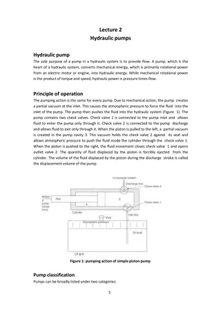
Priming of centrifugal pump The operation in which the suction pipe, casing of pump and a portion of delivery pipe is filled by the outside source of liquid before starting the pump. Foot value is necessary at the end of suction pipe to fill water in the pipe for priming. This process removes air from impeller and casing necessary for pumping of liquid.
Terminologies Associated to Pumping Systems Static Suction Head (hs): It is the vertical distance between the centre of the impeller to the free surface of the water from where water is to be pumped. If the liquid level is above pump centerline, hsis positive. If the liquid level is below pump centerline, hsis negative. Negative hs condition is commonly denoted as a suction lift . Static Discharge Head (hd): It is the vertical distance between the pump centerline and the point of free discharge or the surface of the liquid in the discharge tank. Total Suction Head (hs): It is the suction reservoir pressure head (hps) plus the static suction head (hs) plus the velocity head at the pump suction flange (hvs) plus the friction head in the suction line (hfs). HS= hps+ hs+ hvs + hfs Total Discharge Head (hd): It is the sum total of discharge reservoir pressure head (hpd), static discharge head (hd), the velocity head at the pump discharge flange (hvd) and the total friction head in the discharge (hfd). Hd= hpd+ hd+ hvd+ hfd Manometric head: It is defined as the head against which a centrifugal pump has to work. Hm= hs+ hd+ hfs+ hfd+ v2/2g
Pump Performance Characteristics The operating characteristic curves of a centrifugal Pump consists of variation of head ( hm), efficiency, power (P) and speed (N) with respect to discharge (Q) The main characteristic curves of a centrifugal pump consists of variation of head (hm), power (P) and discharge (Q) with respect to speed. If Impeller diameter D is held constant: Q N, H N2 and P N3 If Similar pumps with speed N is constant Q D3, H D2 and P D5 Therefore, Q ND3, H N2D2 and P N3D5 Power supplied to the pump drive = Mass flow rate x ( Hd Hs)/ , where , is efficiency of pump, Hd= total discharge head and Hs= Total suction head
Pump Efficiency Pump efficiency: It is a measure of the efficiency with which the pump uses the input power to convert the energy into useful output. = Pout/Pin Water Horse Power (WHP) and Brake Horse Power (BHP) :The work performed by a pump is a function of the total head and the weight of the liquid pumped in a given time period. Pump input or brake horsepower (BHP) is the actual horsepower delivered to the pump shaft. Pump output or hydraulic or water horsepower (WHP) is the liquid horsepower delivered by the pump. BHP = g H Q/ or efficiency, = WHP/BHP The head added by the pump (H) is a sum of the static lift, the head loss due to friction and any losses due to valves or pipe bends all expressed in metres of fluid.