Explore the function and applications of Zener diodes, semiconductor devices that conduct in both directions. Learn about forward and reverse bias, zener voltage, and how zener diodes are used as voltage regulators in electronic circuits.
Please find below an Image/Link to download the presentation.
The content on the website is provided AS IS for your information and personal use only. It may not be sold, licensed, or shared on other websites without obtaining consent from the author. If you encounter any issues during the download, it is possible that the publisher has removed the file from their server.
You are allowed to download the files provided on this website for personal or commercial use, subject to the condition that they are used lawfully. All files are the property of their respective owners.
The content on the website is provided AS IS for your information and personal use only. It may not be sold, licensed, or shared on other websites without obtaining consent from the author.
E N D
Presentation Transcript
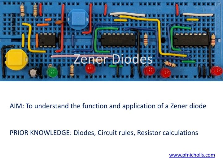
Zener Diodes AIM: To understand the function and application of a Zener diode PRIOR KNOWLEDGE: Diodes, Circuit rules, Resistor calculations www.pfnicholls.com
Overview A zener diode is a type of diode that conducts in both directions. In forward bias a zener diode behaves exactly like a standard silicon diode. In reverse bias a zener diode will conduct and allow current to flow when the applied voltage is greater than the zener voltage. Zener diodes can be identified by the letter "Z" in the name or by having the zener voltage as part of the name. For example a BZX85c5v6 is a zener diode with a zener voltage of 5.6 volts. In the image of zener diodes the blue and red examples are labelled 5v1 and the smaller orange one is labelled BZX.
Forward Bias When the anode is connected to the battery positive the zener diode is forward biased and it behaves in the same way as a silicon diode. The forward bias voltage across the zener diode is 0.7V and the potential difference across the 1k resistor is 5.3V so that a current of 5.3mA flows in the circuit. Just as is the case with LEDs and regular diodes, it is always necessary to be able to calculate the value of the series resistor. This is probably one of the most common calculations in GCSE Electronics
Reverse Bias The cathode is connected to the battery positive, the zener diode is reverse biased. The battery voltage is greater than the zener voltage (5.6V), the zener diode conducts. The voltage drop across the zener diode is maintained at 5.6V and the potential difference across the 1k resistor is therefore 0.4V leading to a circuit current of 0.4mA. In reverse bias, the power dissipated by the zener diode is 5.6V 0.4mA = 2.2mW. The zener voltage is a characteristic of a zener diode. Any given zener diode has a very specific fixed zener voltage. Zener diodes are available in many different zener voltages ranging from 1.8V up to voltages in excess of 100V.
Transfer characteristics In forward bias the current is initially zero when the potential difference is less than 0.6 V. The forward bias potential difference does not exceed much more than 0.7 V when current flows through the zener diode. In reverse bias the current is initially zero when the potential difference is less than the zener voltage. When the potential difference exceeds the zener voltage the current rapidly increases. The reverse bias potential difference across the zener diode is almost constant once current. Note: There must be a few milliamps of current flowing through the zener diode before the reverse bias voltage remains constant as can be seen by the corner on the graph.
Used as a regulator In reverse bias a zener diode acts as a very basic voltage regulator. When the input voltage is greater than the zener voltage the zener diode conducts in reverse bias, current flows through the resistor to ensure the potential difference across the zener diode remains constant. Therefore the output voltage remains constant even when the input voltage changes. When the input voltage is less than the Zener voltage, the output is not constant. The output is less than or equal to the input voltage depending on how much current flows through the load.
Used with a comparator A zener diode can be used as a reference voltage in a comparator circuit. The zener diode in reverse bias and the series resistor provide a fixed voltage at the inverting input of the operational amplifier. In the diagram, this is 5.1 V. When the input voltage is less than 5.1 V the output of the Op-Amp comparator is close to 0 V. When the input voltage is greater than 5.1 V the output of the Op-Amp comparator is close to 9 V. The advantage of using a zener diode to provide a reference voltage rather than a potential divider or potentiometer is that the reference voltage remains fixed even if the power supply voltage fluctuates.
Series resistor calculation A zener diode always needs a suitable series resistor. The resistor value must be low enough to allow adequate current to flow through the zener diode and the circuit (the load). The resistor value must be high enough to avoid damaging the zener diode if too much power is dissipated. There are two situations to consider: Situation 1: Knowing the maximum power handling of the zener diode, calculate a suitable value for the series resistor and then calculate the maximum current that can flow through the load. Situation 2: Knowing what current the load requires, calculate a suitable value for the series resistor and then choose a zener diode with a suitable power rating.
Series resistor: Example 1 A 5.6V zener diode is rated at 500mW. What series resistor is needed for use with a 12V supply? How much current can be provided to the load if the zener diode requires a minimum reverse bias current of 4mA? From the diagram it can be seen that current in the resistor = current in zener diode + current in load. The maximum current will flow in the zener diode, and maximum power will be dissipated, when the load is disconnected and takes zero current. Using I = P V gives IZ = 0.5 5.6 = 0.089A or 89mA. Maximum current that can flow in zener diode must be limited to 89mA Potential difference across the resistor = 12 5.6 = 6.4V When the load takes no current, IR = IZ = 89mA Using R = V I gives R = 6.4 0.089 = 71 (so use 75 from the E24 series) R = 75 and V = 6.4V, the current in the series resistor is I = 6.4 75 = 85mA, therefore the maximum current that can be provided to the load is 81mA (85mA flowing through the series resistor 4mA required by the zener diode)
Series resistor: Example 2 A load requires a steady voltage of 5.1V and a current of 2A. What value of series resistor must be used if the supply voltage is 12V and the zener diode requires a reverse bias current of 20mA? What must be the power rating of the zener diode? The load requires a current of 2A and the zener diode needs 20mA (0.02A) therefore the resistor current is 2.02A The potential difference across the resistor is 12 5.1 = 6.9V Using R = V I gives R = 6.9 2.02 = 3.4 so use the next lowest value (to ensure the minimum current is available) of 3.3 from the E24 series. Using R = 3.3 gives a current of I = 6.9 3.3 = 2.09A In the worst case scenario, when the load is disconnected (IL = 0), all of the current flowing through the resistor must flow through the zener diode. The maximum power rating of the zener diode is given by P = V I and so P = 5.1 2.09 = 10.7W Note:The above example is a very poor way to derive a steady 5 V from a 12 V supply. There are much better methods but the example shows how the calculations should be done.
Summary A Zener diode acts like a normal diode when forward biased In reverse bias, the Zener diode conducts when the potential difference across the diode is greater than the Zener voltage In reverse bias, the potential difference across the Zener diode is constant and so a series resistor is required Zener diodes are specified by their Zener voltage and their maximum power handling A Zener diode is the basis of a voltage regulator Using a Zener diode in a comparator means the reference voltage is independent of the supply voltage
Questions 1. A Zener diode labelled BZX7v2 is forward biased so that current flows. What is the potential difference across the Zener diode? 2. The same Zener diode, BZX7v2 is reverse biased so that a current of 100mA flows. What is the potential difference across the Zener diode? 3. A Zener diode has a reverse bias potential difference of 12V and a current of 300mA flows with no load. What is the minimum power rating of the Zener diode? 4. In question 3, what is the value of the series resistor if the supply voltage is 20V? 5. In question 3, if the Zener diode needs a current of 20mA, how much current is available to the load?
Answers 1. As the Zener diode is forward biased, the potential difference will be 0.7V 2. 7.2V as indicated by the name 7v2 3. All of the current flows through the Zener diode to P = V x I gives Pmin = 12 x 0.3 = 3.6W 4. Potential difference across the resistor is 8V and the current is 300mA so, using R = V I, R = 8 0.3 = 27 5. 280mA