ZepZep C4 Entryway Foam System - Installation Instructions
This manual provides detailed instructions on installing the ZepZep C4 Entryway Foam System, including setup requirements, nozzle placement, unit mounting, supply connections, safety precautions, and usage guidelines. The system is designed for effective foam application in doorways, ensuring proper sanitation and cleanliness. Follow the steps outlined here for a successful installation and operation of the C4 foam system.

Download Presentation

Please find below an Image/Link to download the presentation.
The content on the website is provided AS IS for your information and personal use only. It may not be sold, licensed, or shared on other websites without obtaining consent from the author.If you encounter any issues during the download, it is possible that the publisher has removed the file from their server.
You are allowed to download the files provided on this website for personal or commercial use, subject to the condition that they are used lawfully. All files are the property of their respective owners.
The content on the website is provided AS IS for your information and personal use only. It may not be sold, licensed, or shared on other websites without obtaining consent from the author.
E N D
Presentation Transcript
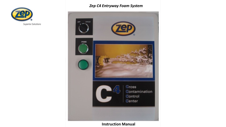
ZepZep C4 Entryway Foam System uctionInstruction Manual
W59901 Stand Alone Unit W60301 Pump Fed Unit Page.2 Installation Instructions Water (40-80 PSI, Minimal 5 GPM) Premix Solution (40-80 PSI, Minimal 5 GPM) Compressed Air (30-100 PSI, 7 SCFM), Clean and Dry Compressed Air (30-100 PSI, 7 SCFM), Clean and Dry Electricity (15 A, 120 VAC) Electricity (15 A, 120 VAC) You will need Sch. 80 pipe, hose clamps, mounting hardware, and fittings to connect the water/solution and compressed air supplies to complete the installation (not included). W59901 Stand Alone Unit W60301 Pump Fed Unit (1) C 4 Foamer Unit 1) C 4 Foamer Unit (1) 5 Feet Blue Discharge hose (1) 5 Feet Blue Discharge hose (1) 6 Feet Clear Pick-Up Hose w/Strainer --- (1) Metering Tip Kit --- (2) Foam Nozzles Assemblies (2) Foam Nozzles Assemblies 1. Open the shipping box and check the contents. If you are missing any parts, please contact your ZEP representative. 2. Determine how many nozzles you will need to cover the doorway. Doors up to 5 feet wide require one nozzle; doors from 5 feet up to 10 feet wide require two nozzles. 3. build the header symmetrically to produce balanced flow and pressure between the nozzles. 4. Mount the C 4 unit on the wall near the door. Connect the discharge of the C 4 unit to the header with a short piece of the discharge hose barb adapters ( included) and the hose clamps (not included). 5. Connect the water supply (stand alone unit) or premixed solution supply (pump fed unit) and compressed air supply water to right side NPT air lift side NPT. Construct a foam header around the door using PVC fittings and PVC pipe are not (included) for two nozzle system,
Page 3 Air supply Minimal 7 CFM Water supply City pressure minimal 40 PSI Ideal. 60-70 PSI Air supply Minimal 7 CFM Water supply City pressure minimal 40 PSI. Ideal 60-70 PSI C 4 Single Doorway Set Up C 4 Double Doorway Set Up 120 VAC 120 VAC Ball Valve Ball Valve Concentrate solution Concentrate solution Safety & Operational Precautions When connecting to a potable water supply follow all local codes for backflow prevention. For proper performance do NOT modify, substitute nozzle, hose diameter or length. Manufacturer assumes no liability for the use or misuse of this unit. Wear protective clothing, gloves and safety goggles when working with chemicals. Always direct the discharge away from people and electrical devices. Never leave inlet ball valves on when unit is not in use. .Follow the chemical manufacturer's safe handling instructions. NEVER mix chemicals without first consulting chemical manufacturer.
Page.4 Metering Tip Chart for the C 4 Entryway foam Sanitizer Gray Injector Body Zep Product # W29301 3 GPM OZ/GAL RATIO Lt Brown 0.25 512.0 Orange 0.50 256.0 Lt Green 0.75 170.7 Purple 1.00 128.0 Lt Blue 1.50 85.3 Peach 2.00 64.0 Red 3.00 42.7 Blue 4.00 32.0 Gray 5.00 25.6 Brown 7.00 18.3 Black 10.00 12.8 Dk Green 13.00 9.8 Pink 18.00 7.1 Yellow 22.00 5.8 White 25.00 5.1
Page. 5 NOTE; it is always best to determine the actual flow rate though flow the injector and base your Calculation on that result. It is also recommended that you confirm your metering tip choicewith a pull test. 1. Thread the metering tip into the metering tip adapter on the sanitizer unit. Connect the pick up hose to the metering tip adapter and place the strainer into the product container. 2. Open the sanitizer unit and close the needle valve by turning the knob to the right until it stops. 3. With the OFF-CYCLE switch in the OFF position, press and hold the PRIME button until the pick-up hose is full and the solution is flowing consistently though the foam nozzle(s). 4. Release the PRIME button. 5. Check the water pressure Gauge. The water pressure must be at least 40 PSI for the sanitizer unit to operate properly (50-60 PSI is ideal). 6. Using the air Pressure regulator and gauge, set the air pressure 10-15 PSI lower than the water pressure. For example, if the water pressure is 60 PSI, set the air pressure at 45 PSI. 7. Press and the PRIME button again until the solution is flowing consistently though the foam nozzle(s). 8. While pressing the PRIME button, adjust the foam quality by slowly increasing the air volume with the needle valve (DO NOT adjust the air pressure regulator). 9. Release the PRIME button and open the panel door to access the cycle timer. 10. Turn the outside knob (green) to the desired (off ) time. (The off) time scale is 10 minutes. 11. Turn the inside knob (red) to the desired (on) time. The (on) time scale is 10 seconds. EXAMPLE: The (off) time is set for 10 minutes; the (on) time is set for 7-8 seconds. 12. Close the panel door and turn the OFF-CYCLE switch to the CYCLE position. The C 4 Entry Foam Sanitizer will now operate automatically. NOTE; The timer will always start with the off cycle when power is supplied.
Troubleshooting Guide Page. 6 1 2 3 4 5 6 7 8 9 10 11 12 13 14 Problems Will not draw chemical x x x x x x x x x Poor foam quality x x x x x x x x x Foam surges and/or sputters x x x x x x x x x x x x Foam output too wet x x x x x x x x x x x Foam output too dry x Water flowing into container x Unequal solution flow (2) nozzles x Chemical pick-up hose is not immersed in the chemical supply or chemical supply is depleted- Immerse the hose in the chemical or replenish the chemical supply. Air Pressure/volume is too high for available water pressure Adjust the air regulator and/or needle valve. Water pressure is too low At least 40 PSI is required, increase the water pressure if possible or decrease the air pressure/volume. Chemical-to-water ratio is too low Correct the chemical-to-water ratio with a larger metering tip. Foam hose or pipe is the wrong size or too long The hose or pipe must be I.D and no more than 50 long. Replace it with the correct I.D and/or shorten to overall length. Inadequate air supply Open the air inlet valve fully and check the needle valve. Wrong chemical is being used Ensure that the chemical is recommended for the application. Use of a lubricator on the air supply may decrease foam quality Use only clean, dry air. Pin hole/cut in the chemical pick-up hose Replace the hose. 10. Chemical Strainer or metering tip is blocked Clean or replace the strainer and/or metering tip. 11. Chemical check valve is not working Clean or replace the check valve. 12. Needle valve or air pressure regulator has failed Clean or replace the needle valve and/or regulator 13. Water scale or chemical build-up may have formed in the injector Remove injector and soak in descaling acid. 14. Foam nozzle branches are not equal in length Reinstall the hose or pipe so that each nozzle branch is approximately the same length. 1. 2. 3. 4. 5. 6. 7. 8. 9.
Page.7 Replaceable Parts Breakdown NPT Air regulator Part #W61601 Water Gauge NPT Part# W61201 1/8 NPT Air Gauge Part # W61301 6 1/4 NPT Air Solenoid Valve Part # W61101 NPT air Water Solenoid NPT 120 Volt Part # W61401 NPT Check Valve Part # W51301 Injector Body Part # T43001 NPT needle Valve adjustment for foam Quality Part # FM00332 NPT St Elbow Part # CE00560 NPT Check Valve Part # W51301 8-Pin Relay Base Part #CE00356 Metering Tip Holder Part # CE00532 ID Pick up Hose Part # S82401 by ft. Cycle Timer Part # W60901
C 4 Parts and Accessories Page. 8 Description Zep # W60101 10 Ft. Power Cord W60901 Repeat Cycle Timer W61801 Green Prime Switch W61901 Green Indicator Light W62001 Off-Cycle Switch W62201 Foam Nozzles W62101 S82401 8-Pin Relay Base Vinyl Tube (Per Ft.) W62501 Swivel Nozzle Holder FM00332 CE00536 Needle Valve NPT Wye Strainer W29301 Metering Tip Kit W61401 Water Solenoid NPT 120 VAC W61101 Air Solenoid NPT 120 VAC All parts may be ordered by calling your local ZEP Rep or 877-I-BUY-ZEP (877-428-9937).