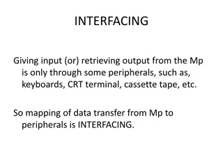
Understanding Data Acquisition and Instrument Interface

In the realm of data acquisition and instrument interface, various components come together to sense physical variables, condition electrical signals, convert analog to digital data, and analyze the acquired information. This process involves transducers, signal analysis, instrument automation, and more. Signal conditioning is crucial for enhancing signal quality before conversion to digital format. Transducers play a key role in converting physical phenomena into electrical signals, while actuators control process equipment. Explore the intricate workings of data acquisition systems through diagrams and detailed explanations.

Uploaded on Apr 05, 2024 | 2 Views
Understanding Data Acquisition and Instrument Interface
PowerPoint presentation about 'Understanding Data Acquisition and Instrument Interface'. This presentation describes the topic on In the realm of data acquisition and instrument interface, various components come together to sense physical variables, condition electrical signals, convert analog to digital data, and analyze the acquired information. This process involves transducers, signal analysis, instrument automation, and more. Signal conditioning is crucial for enhancing signal quality before conversion to digital format. Transducers play a key role in converting physical phenomena into electrical signals, while actuators control process equipment. Explore the intricate workings of data acquisition systems through diagrams and detailed explanations.. Download this presentation absolutely free.
Presentation Transcript
Chapter 2 Data Acquisition and Instrument Interface
Contents Data acquisition Instrument automation system Building blocks Signal analysis I/O port configuration with instrument bus protocols ADC/DAC,DIO, counters/times, PC hardware structure, timing, interrupts, DMA, software and hardware installation, Programming and simulation of Instrument automation
Data Acquisition System A data acquisition system consists of many components that are integrated to: Sense physical variables (use of transducers) Condition the electrical signal to make it readable by an A/D board Convert the signal into a digital format acceptable by a computer Process, analyze, store, and display the acquired data with the help of software
Data acquisition system Schematic diagram of a typical DAQ system
Data Acquisition System Block Diagram
Transducers Sense physical phenomena and translate it into electric signal. Temperature Pressure Light Force Displacement Level Electric signals ON/OFF switch
Transducers and Actuators A transducer converts temperature, pressure, level, length, position, etc. into voltage, current, frequency, pulses or other signals. An actuator is a device that activates process control equipment by using pneumatic, hydraulic or electrical power. For example, a valve actuator opens and closes a valve to control fluid rate.
Signal Conditioning Signal conditioning circuits improve the quality of signals generated by transducers before they are converted into digital signals by the PC's data-acquisition hardware. Examples of signal conditioning are signal scaling, amplification, linearization, cold-junction compensation, filtering, attenuation, excitation, common-mode rejection, and so on.
Signal Conditioning One of the most common signal conditioning functions is amplification. For maximum resolution, the voltage range of the input signals should be approximately equal to the maximum input range of the A/D converter. Amplification expands transducer signals so that they match the input range of the A/D converter. For example, a x10 amplifier maps transducer signals which range from 0 to 1 V into the range 0 to 10 V before they go into the A/D converter. the range of the
Signal Conditioning Electrical signals are conditioned so they can be used by an analog input board. The following features may be available: Amplification Isolation Filtering Linearization
Data Acquisition Data acquisition and control hardware generally performs one or more of the following functions: analog input, analog output, digital input, digital output and counter/timer functions.
Analog Inputs (A/D) Analog to digital (A/D) conversion changes analog voltage or current levels into digital information. The conversion is necessary to enable the computer to process or store the signals.
Analog Inputs (A/D) The most significant criteria when selecting A/D hardware are: 1. Number of input channels 2. Single-ended or differential input signals 3. Sampling rate (in samples per second) 4. Resolution (usually measured in bits of resolution) 5. Input range (specified in full-scale volts) 6. Noise and nonlinearity
Analog to Digital (A/D) Converter Resolution Range Gain Input signal Sampling rate Throughput
A/D Converter: Sampling Rate Determines how often conversions take place. The higher the sampling rate, the better. 16 Samples/cycle 8 Samples/cycle Analog Input 4 Samples/cycle
A/D Converter: Sampling Rate Aliasing. Acquired signal gets distorted if sampling rate is too small.
A/D Converter: Throughput Effective rate of each individual channel is inversely proportional to the number of channels sampled. Example: 100 KHz maximum. 16 channels. 100 KHz/16 = 6.25 KHz per channel.
A/D Converter: Range Minimum and maximum voltage levels that the A/D converter can quantize Ranges are selectable (either hardware or accurately measure the signal software) to
Analog Outputs (D/A) The opposite of analog to digital conversion is digital to analog (D/A) conversion. This operation converts digital information into analog voltage or current. D/A devices allow the computer to control real-world events. Analog output signals may directly control process equipment. The process can give feedback in the form of analog input signals. This is referred to as a closed loop control system with PID control. Analog outputs can also be used to generate waveforms. In this case, the device behaves as a function generator.
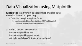
Data Acquisition Software It can be the most critical factor in obtaining reliable, high performance operation. Transforms the PC and DAQ hardware into a complete DAQ, analysis, and display system. Different alternatives: Programmable software. Data acquisition software packages.
Programmable Software Involves the use of a programming language, such as: C++, visual C++ BASIC, Visual Basic + Add-on tools (such as VisuaLab with VTX) Fortran Pascal Advantage: flexibility Disadvantages: complexity and steep learning curve
Data Acquisition Software Does not require programming. Enables developers to design the custom instrument best suited to their application. Examples: TestPoint, SnapMaster, LabView, DADISP, DASYLAB, etc.
Designing a DAS: Factors to Consider Is it a fixed or a mobile application? Type of input/output signal: digital or analog? Frequency of input signal ? Resolution, range, and gain? Continuous operation? Compatibility between hardware and software. Are the drivers available? Overall price.
SCADA system Supervisory needs- Control actions need confirmation Data acquisition +supervisory control=SCADA Basic elements Interface in the field Scan interfaces (real and reactive power, current, voltage, switch and CB position) Transmission to central station Processing and display Determine control actions Transmitting request for control to the field equipment Monitoring the completion of control request Building data base
Anatomy of SCADA Control center main computer, router, data historian, HMI and engineering workstation Collect data, analyze trends and events, generates action Communication link any long distance communication system: fiber, cable and RF Serial communication protocol Filed sites RTU or PLC Local control of actuators
SCADA communication Point to point- takes many communication channel Series good in simplicity but channel sharing has problems Series star- one channel per device, decreased efficiency and increase system complexity Multi drop same as series star
Implementation Examples A SCADA system with one primary control and three field sites Control center to field site communication takes place using point to point Radio telemetry WAN Backup control is provided for redundancy Field sites can be accessed through WAN for maintenance
Railway control using SCADA
Instrument automation There are four basic classes of instrument automation system Industrial automation system Building automation system Power system automation Process automation system
Protocols and Standards Data comm. Involves transfer of data from source to destination Data can be Analog- telephone lines Digital modern comm. Systems Receiver and Transmitter should agree on how data is encoded . This agreement is known as a protocol
OSI model Is communication It has seven layers- each layer has its own interface and protocol a layered architecture for data
OSI model The main part of the OSI model is the protocol Protocol defines how data is to be framed for transmission Protocol format
RS 232 Standard Interface Defines the standard electrical and mechanical interface between DTE and DCE It defines serial communication interface Serial data communication
RS 232 standard It supports Both half duplex Full duplex communication In the industry it is used to interface PLC with other PLC RTU with main computer
MODBUS and other standards Is an application layer protocol Supports comm. between client/server Where there is different types of buses or networks It does not specify any specific hardware It has modbus request and modbus reply messages
Modbus contd The parameters exchanged between client and server have What to do, function code function code With what input or output data exchange There are classes of function code Class 0 useful commands for both client and server Read registers Write registers
Modbus protocol Class 1 interoperable set of commands Read coils Read input discrete Read input registers Write coils Force single coil Class 2- comprises the data transfer functions for routine operation force multiple coils Read/write registers
Modbus plus Is a modbus protocol with specific hard ware Used for LAN connection of industrial system It can be used to control a remote device
Device net and its accessories Device net is low level device oriented network It can connect sensors and actuators with controllers It is based on controller area network which uses multi-byte message format It can support up to 64 nodes Four conductor cable provides both power and data communication
Device net It supports baud rates of 125,250 and 500K baud It implements layer 3 and layer 4 It is a routable system
Profibus Its name comes from process field bus Is widely accepted standard common in process control and in large assembly and material handling systems It allows single cable wiring of multi-input sensors, pneumatic valves, complex intelligent devices, smaller sub-networks and operator interface


")
")
 Converter")


")
")