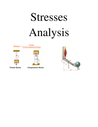
Insights from Summer Engineering Internship on Formwork Stress Distribution

Hemang Sheth's final presentation for the summer internship at SGAWINGS Civil Engineering Consultant & Advisor covers a detailed exploration of vertical stress distribution on formwork components in infrastructural projects. Topics include factors affecting stress distribution, components of formwork, and learning outcomes related to strength, stiffness, and durability analysis. The presentation delves into the intricacies of stress trajectories, beam design effects, and practical considerations for concrete pouring rates and temperatures.
- Formwork Stress Distribution
- Engineering Internship
- Concrete Pouring
- Beam Design
- Structural Analysis

Download Presentation

Please find below an Image/Link to download the presentation.
The content on the website is provided AS IS for your information and personal use only. It may not be sold, licensed, or shared on other websites without obtaining consent from the author. Download presentation by click this link. If you encounter any issues during the download, it is possible that the publisher has removed the file from their server.
E N D
Presentation Transcript
SUMMER INTERNSHIP(MAY23) FINAL PRESENTATION By: Hemang sheth Submitted to :SGAWINGS CIVIL ENGINEERING CONSULTANT & ADVISOR (OPC.) PVT. LTD., Mumbai
WHAT I HAVE LEARNED Vertical stress distribution on formwork Component of formwork in infrastructural project Improved basic fundamental of inertia forces. Slab yielding lines of different shapes. Understanding in depth difference between strength , stiffness, ductility, and durability. Stress trajectory distribution In beam. Effect of Xu on double and singly beam designs.
FACTORS AFFECTING STRESS DISTRIBUTION IN VERTICAL FORMWORK. Pour rate of concreting generally (1 m/hr.) Depth of pouring Temperature (suitable at room temperature between 20 to 27 degree Celsius) Note: after some depth the concrete pressure becomes constant at does not increase.
COMPONENT OF FORMWROK Skin plate Horizontal stiffener Vertical stiffener Waler Jacks Bulk head Eye plate
SKIN PLATE jacks VERTICAL STIFFNER TIE RODS
WALER Waler
STIFFENERS AND BULK HEAD Horizontal stiffener: They are rectangular in shape thickness varying from 3-6 mm . They are perpendicular to vertical stiffeners. They prevent bending of skin plate along its major axis. Vertical stiffener: Vertical stiffener provides minor axis stability of skin plate They are may be angle section or hollow rectangular section
CONTINUED. Bulk head: They are the end member of formwork to support fresh concrete to come out from its ends. Bulk head design done in such a way that it can resist load about minor axis of girder. Minor axis(its nothing but resist less load with respect to major axis) Front view Side view
SLABS There are different types of yielding line based on that load on beam can be calculated. Maximum reinforcement 0.15% in case of mild steel bar However this percentage can be reduce to 0.12% in case of HYSD bars.
BEAMS There are two types of beams 1. Singly beams 2. Doubly beams
SINGLY BEAMS Singly beams neutral axis is taken maximum and designed as balanced section. Singly beams concrete compression force is equal to tension steel. In singly beam if we increase the grade of the concrete the depth of neutral axis becomes larger as the depth of neutral axis increase moment carrying capacity also increase. Grade of the concrete(N/mm^2) Depth of neutral axis(mm) Moment carrying capacity (kN/m) 20 175.20(max depth of axis) 128.97 30 119 142 35 103 145 40 90 149 NOTE:ASSUMING SECTION SIZE 350*400 and tension steel as 0.89%
CONTINUED. From above table we can interpret that grade of concrete is inversely proportional to depth of neutral axis and proportional to moment carrying capacity if section and percentage of steel is fixed. Now, if we fix the grade of concrete moment carrying capacity proportional to percentage of tension steel up to limiting area of steel. hence the grade of concrete is inversely proportional to depth of neutral axis and proportional to moment carrying capacity proportional to area of tension reinforcement.
DOUBLY BEAM There are two types of forces in compression side concrete compression and steel compression is must be equal to tension side steel forces. We cant take neutral axis more then Max depth of neutral axis. If area of reinforcement is more than the limiting area of reinforcement then section becomes over reinforced section in that first steel failure is taking place that is not generally practise so generally prefer under reinforced section because it is advisable that if collapse is taking place some indication is there.
COTD. Also, we can increase the moment carrying capacity by increasing the depth of neutral axis till neutral axis is maximum we can go after that it becomes over reinforced means sudden failure of concrete. So keeping in mind these all the points or concept we have to choose under reinforced section.
MOHRS THEORY There are two types of stresses shear stress and flexure stresses. Flexure stress is happening where bending is taking place in flexure members it depends upon in section modulus of section and bending moment at that place. Shear stresses is vertical load in member it is depend upon the gravity load applied over unit area So assume one beam having length l and load w kN/m over entire span. In that case flexure stress is maximum in compression top layer.
CONTINUED In this section aa flexure stress is maximum and shear stress is xero by plotting Mohr s circle. Now in section BB shear is happening in some amount and some flexture stress also in some amount. While in section CC shear stress is maximum and flexure is zero.
STRESS TRAJECTORY PRINCIPAL Compression stress Shear stress Tensile stress
MOHRS CIRCLE Flexure stress diagram
SHEAR STRESS DIAGRAMS Shear stresses diagram for section AA,BB,CC.
CONTINUED. From stress trajectory principal clearly shows that at section AA shear stress will be zero so Mohr's circle has only bending stress circle. While at section BB both stresses is acting so there we will get resultant stress by plotting bending and shear stress diagram. Procedure will be discussed in upcoming slides. At section CC no bending stress will occur only shear force is acting hence resultant will be in vertical direction only.
PROCEDURE FOR PLOTTING MOHR'S CIRCLE Through suitable scale plot bending stress in x direction and shear force from that point in vertical direction connect those shear force point and make a circle t will give you the resultant force in any direction
MOST IMPORTANT: Strength Stiffness Durability Ductility
STRENGTH Material load carrying capacity ill increase or decrease with the variation in this para meters. Suppose M35 is more stronger than M25. Where geometry of structure is restricted we can increase stengh by in incrasing this parameters
STIFFNESS Stiffness is deal with the geometry of structure , any structure we can increase the load carrying capacity by extending its length width and height parameters. So material is not available in sufficient quantity than we have to change the dim. In general stiffness of structure is Stiffness is the extent to which an object resists deformation in response to an applied force.
DURABILITY & DUCTILITY. Its depend on the structural state in analysis. Includes structural safety and structural durability. he extent to which a material (or structure) can undergo large deformations without failing. The term is used in earthquake engineering to designate how well a building will endure large lateral displacements imposed by ground shaking
SUMMARY I have learn many practical aspects in structural engineering Improved fundamentals like orientation of structural member impacts on load carrying capacity Some of the not known things like formwork code of different county I also get to know. I have improves sheet of bridge girder design. Overall experience was so amazing I am grateful and thankful to Vivek sir for giving me this wonderful opportunity. Thank you.
 FINAL PRESENTATION")