Crystal Field Theory in Transition Metal Complexes
Crystal Field Theory (CFT) explains the colors and magnetic properties of transition metal complexes. It focuses on the energy changes in d-orbitals of metal ions caused by surrounding ligands. This theory, developed in 1929, provides insights into the bonding interactions in complex compounds. The shapes of d-orbitals, crystal field splitting in octahedral, tetrahedral, and square planar complexes, high spin vs. low spin configurations, and molecular orbital theory for octahedral complexes are key topics in CFT.

Crystal Field Theory in Transition Metal Complexes
PowerPoint presentation about 'Crystal Field Theory in Transition Metal Complexes'. This presentation describes the topic on Crystal Field Theory (CFT) explains the colors and magnetic properties of transition metal complexes. It focuses on the energy changes in d-orbitals of metal ions caused by surrounding ligands. This theory, developed in 1929, provides insights into the bonding interactions in complex compounds. The shapes of d-orbitals, crystal field splitting in octahedral, tetrahedral, and square planar complexes, high spin vs. low spin configurations, and molecular orbital theory for octahedral complexes are key topics in CFT.. Download this presentation absolutely free.
Presentation Transcript
Chapter 2 Ligand Bonding In Transition Metal Complex Metal Complex Metal Metal- -Ligand Bonding In Transition Contents 1. Crystal field theory(CFT) 2. Introduction: Shapes of d-orbitals, Basic assumptions of CFT. 3. Crystal field splitting of d-orbitals of metal ion in octahedral, tetrahedral, square planar complexes andJohn-Teller distortion. 4. Factors affecting the Crystal field splitting. 5. High spin and low spin octahedral complexes w.r.t. Co (III). 6. Crystal Field stabilization energy (CFSE), Calculation with respect to octahedral complexes only. 7. Limitations of CFT. 8. Molecular orbital theory (MOT). 9. Introduction. 10. MOT of octahedral complexes with sigma bonding such as [Ti(H2O)6]3+,[CoF6]3 , [Co(NH3)6]3+. 11. Merits and demerits of MOT. [ [10 10] ]
2.1. Crystal field theory (CFT) : Introduction :- The crystal field theory was first applied by the physicists H. Bethe and J. Van Vleck in 1929 to explain the colours and magnetic properties of crystalline ionic solids. So it is often called crystal field theory, CFT. entirely of ionic or electrostatic type. In other words, the they accepts total absence of covalent bonding. Although CFT was developed nearly at the same as that of VBT, it was not seriously applied by chemists until the 1950s. By then, it was used to interpret spectra of transition metal complexes, where VBT was in failure. And CFT was accepted to be a better semi quantitative approach to explain many of the observed properties of co-ordination compound. This theory assumes the bonding between metal ion and the ligands to be modification produced in the energies of the d-orbital of the metal atom / ion by the surrounding ligands. In other words, such interaction between metal ion d-orbitals and the surrounding ligands are termed as the crystal field effects and the theory as crystal field theory. Further, the theory assumes that the properties of complexes stem from the
Shapes of d-orbitals, Basic assumptions of CFT. (i)Shapes of d-Orbitals shapes and orientations in space, in order to understand clearly the interactions that are responsible for the crystal field effects. The valence electrons in transition metal ion move preferentially in d-orbitals and hence they are of more concern to us. In a complex formation, d-orbitals play an important role. It becomes, therefore, essential to study their There are five d0orbitals in metal viz. dxy, dyz, dzx, dx2 y2 and dz2. All the five orbitals are not identical but they fall into two categories : t2g and eg ; where t stands for three fold degeneracy of dxy, dyz and dzx and e stands for two fold degeneracy of dx2 - y2 and dz2 whereas g speaks of German term gerade meaning even. The two sets are : 1. The set of three orbitals which point in between the x and y, y and z, and z and x axes and which are equivalent to each other are called t2gor d ( dee epsilon), orbitals and are designated as dxy, dyz and dzx respectively. The set of two orbitals which lie on the x and y ; and the z axes and which are equivalent to each other are called eg or d (dee gamma) orbitals and are designated as dx2 y2 and dz2 respectively. With all specifications, the five d- orbitals may be depicted as in fig. 2.1 Fig. 2.1 : Shapes of d-orbitals
The lobes of the orbitals bear + and signs. These refer to the signs of the wavefunction and should not be confused with type of charge. We should not forget that the electron is a cloud of negative charge. These signs are important from the point of view of the formation of the bonds between atoms. Fig. 2.2 : A linear combination of the dz2 x2 and dz2 y2 orbitals giving dz2 In fact, one may expect six wave functions for the d-orbitals having the typical four-lobed form. But from physical reality, we have only five d-orbitals. The fifth dz2 orbital is a linear combination of the other two orbitals , dz2 y2 and dz2 x2. Since both have electron density along the z axis, the dz2 orbital has a large amount of electron density concentrated along the z axis and only a tours (doughnut or belly band) i.e. a ring or belt of electron density in the xy plane as shown in above fig. 2.2
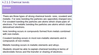
(ii) Basic Assumptions of CFT To have the clear mental picture of the CFT, one must be conversant to its following assumptions : The ligand act as the point negative charges, whether they may be ionic (Cl-, Br-, SCN-, etc.) or molecular (H2o, NH3, etc). For neutral molecular ligands, dipoles are formed where the negative end of the dipole is oriented towards the positive metal ion. In short, a ligand lone pair is modeled as a point negative charge. 1) 2) There is neither electron sharing nor orbital overlap between metal atom and the ligands. 3) The five d-orbitals of the metal having equal energy (i.e. degenerate) in an isolated atom, get their degeneracy split by the approaching ligands when a complex is formed. 4) In complex formation, the transition metal is positioned as a central cation which is surrounded by a group of ligands having lone pairs of electrons. 5) The number of ligands and their arrangement around the central metal ion determine the crystal field. 6) Different crystal field have different effects on the relative energies of the five d-orbitals. 7) The ligands repel the valence electrons in the d-orbitals of central metal. Hence these d-electrons try to occupy those d-orbitals having their lobes farthest away from the direction of approaching ligands. 8) CFT principally concern with the interactions of the d-orbitals of central metal with the surrounding ligands that produce crystal field effects.
2.1.2. Crystal field splitting of d-orbitals of metal ion in octahedral, tetrahedral, square planar complexes and John-Teller distortion. The splitting of the five degenerate-d orbitals of the free metal ion, into groups having different degenerate d-orbitals energies, due to ligand field is known as crystal field splitting or ligand field splitting. The concept of ligand field splitting forms the sole basis or the primary feature of crystal field theory. The effect of ligand field on the d-orbitals of the metal depends upon the nature and direction of ligands. Let us have an insight of crystal field splittings in the complexes having octahedral, square planer and tetrahedral geometries. 1. Crystal Field Splitting in Octahedral Complexes Let us consider the formation of an octahedral (i.e. six co-ordinated) complex. See fig. 2.4.The ligands are assumed to approach the metal ion along the Cartesian co- ordinate axes. In an octahedral complex the metal is at the centre of the octahedron while the ligands are at six coners where x, y, z, -x, -y, and z point to the corners of the octahedron. The dx2 y2 and dz2 (eg) orbitals are directed along the three axis while the dxy,dyz and dxz(t2g) orbitals are in between the x and y, z and z and z and x axes as shown in fig. 2.3
Fig. 2.4 : Formation of an Octahedral Complex. The approach of six ligands along the axial directions as shown in fig 2.4 will increases the energy of the eg orbitals much more than the t2g orbitals. Thus under the influence of the octahedral ligand field, the sets of five free uncomplexed degenerate d-orbitals split into two groups of different energies, (eg and t2g ) is known as the crystal field splitting, or ligand field splitting. This is the primary feature of CFT and may be shown in the form of energy level diagram as depicted in fig 2.5. Compare this figure with fig.2.3
Fig. 2.5 Crystal field splitting of energy levels in octahedral field The difference (or separation ) in energy between the two sets of d-orbitals is given by either of the symbols (delta), or 10 Dq and it is called the crystal field splitting parameter. from the average level, say by +0.6 o (or 6Dq) and the t2g set should go down from the average level say by -0.4 o or (-4 Dq). Thus every electron in eg is destabilized by (+6 Dq) and every electron in t2g is stabilized by (-4 Dq). When all the orbitals are filled with 10 electrons, 6 in t2g and 4 in eg , the change in energy would be : Since the pre-splitting barycentre or centre of gravity is to be maintained, the eg set should go up -24 Dq + 24 Dq = 0 The energy of barycentre is thus maintained and the complex becomes stable. occupy the lower energy grouporbitais t2g. Consequently, the energy of the resulting complex is lowered by -4 Dq units, as compared to the free metal ion and thus complex gains stability. For example : A single electron in Ti3+ ion under the influence of six ligands, say in [Ti(H2O)6]3+, would
2. Crystal Field Splitting in Tetrahedral Complexes imagined to occure in much the same way as octahedral complexes. Crystal field splitting of the d-orbitals for the tetrahedral structure is rather difficult to visualize. Consider a tetrahedron inside a cube whose edges are parallel to the x, y and z axes so that they go through the centre of the cube and point to its six face centres as shown in fig. 2.6 The formation of tetrahedral complexes can be Fig. 2.6 : Tetrahedral arrangement of 4 ligands around a metal ion Consider a central metal ion at the centre of the cube whose alternate corners are occupied by the four ligands and thus the geometry adopted by the complex is tetrahedral one. In such arrangement, when the four ligands approach the central metal, they do not come along the axes. Hence these ligands will affect the t2g orbitals more than the eg orbitals. To maintain the barycentre, t2g orbitals are raised by 4 Dq while eg orbitals are lowered by -6 Dq. Thus the energy level scheme for tetrahedral symmetry is exactly reversed of the octahedral symmetry. Fig. 2.7 Crystal Field Splitting of d-orbitals in Tetrahedral field
It has been observed that number of ligands in tetrahedral complexes being less than in octahedral complexes and as the d-orbital are not directly affected, the interaction of the approaching ligands with those of d-orbitals would be weaker. The energy separation between t2g and eg orbitals (i.e. t ) or 10 Dq (Td) is expected to be less than that observed for octahedral field (i.e. 0 ). If the central metal ion, ligands and the distance between them are all same in both octahedral and tetrahedral complexes, we get : t = 4/9 0 (i.e. 0.45 0 ) Because the 10 Dq value is low in tetrahedral symmetry, the crystal field favours the formation of octahedral complexes than tetrahedral complexes.Tetrahedral complexes are favored only when both eg and t2g are symmetrical i.e. empty, half-filled or completely full. For example d0, d1, d2, d5, d7 and d10 systems. e.g. d0 [TiCl4] ; d5 [FeCl4]-, d10 [ZnCl4]2-.
3. Crystal Field Splitting in Square Planar Complexes from octahedral complexes, a square planer complex is formed. In square planer complex, there are four ligands at the four corners of a square in XY plane, on X and Y axes. See the fig. 2.7 . When the ligands approach along the X and Y axes so as to form a square planar complex, the degeneracy of the five d-orbitals is split. The ligand field interaction with the metal ion d-orbital will be different depending on their orientations as shown in fig. 2.1 It will be strongest with dx2 y2 orbital lying on X and Y axes; a little less with dxy orbitals that lies in between X and Y axes and still lesser with dz2 orbital oriented along Z axis, and least for dyz and dzx, due to their orientation in the yz and zx planes. The crystal field splitting in suareplaner complex may be shown as in fig. 2.8 As a result of some distortion, when the two ligands on z axes are completely removed (a) d8 configuration in strong ligand field (b) CF Splitting where dz2 is very full and dx2 y2 is empty. Fig. 2.8 : Crystal Field Splitting in Square planer complex splitting in octahedral ligand field. The details have been shown in fig. Some typical example having square planer geometry are of metal ions with d8 configuration. For example [Ni(CN)4]2-, [Pt (NH3)4]2+, [PtCl4]2- , etc. This splitting of d-orbital is much larger as compared to
4. John-Teller distortion : and Teller, known as John-Teller Theorem or John-Teller effect. It states that for a non-linear molecule, distortion must occure in the degenerate state of orbital due to (metal) electron and (ligand) electron repulsion to lower the symmetry, remove the degeneracy, and lower the energy. In 1937, a remarkable observation was made by Jahn symmetrically w.r.t. the octahedral ligand field, a completely regular octahedral structure is formed e.g. d0 ,d3 and d10 strong and weak field complexes; d5 and d8 weak field and d6 strong field complexes say [TiF6]2- , [ Cr (H2O)6]2+ , [Zn (NH3)6]2+, [FeF6]3 and [Ni(H2O)6]2+ ; [Fe (CN)6]4- complexes respectively. But when d-orbitals, especially eg orbitals, are filled asymmetrically, a significant distortion occurs in the octahedral shape. eg d4, d7 and d9 configurations. The degeneracy of e.g. level is removed // split. The dx2 y2 orbital, having four lobes, is increased in energy while the dz2 orbital with only two lobes pointing at the ligands is decreased in energy. The distortion caused by such an arrangement of electrons say (dz2)2 (dx2 y2 )1 i.e. d9 or (dz2)1 (dx2 y2)0 i.e. high spin d4, results in a complex with four short bonds in the x and y directions with two longer bonds along the z axis. When the d-electrons are arranged Fig. 2.9 : Tetragonal ML6 complex Fig. 2.10 : Crystal Field splitting in Tetragonal Ligand Field
The octahedron is said to have undergone tetragonal distortion. Such distortion, resulting in splitting of energy levels yields additional stabilization. It is known as Jahn Teller Effect causing Jahn Teller distortion leading to Jahn Teller splitting associated with Jojn-Teller Stabilization Energy, explained by Jahn Teller theorem is shown in fig for d9 system, Cu (II). approaching along the X and Y axes. As the high energy dx2 y2 orbital is only singly occupied and the lower energy dz2 is doubly occupied there is an additional stabilization over the regular octahedron. Thus, the energy of the system is lowered. The crystal field splitting of d-energy levels in distorted octahedral ligand field results from their splitting. The t2g orbitals are even split, but being completely filled, no stabilization t2g. the magnitude of 1 and 2 is very small as compared to 0 >>> 1> 2.see fig. 2.10 Let 0 be splitting of t2g and eg for octahedral field, 1 for eg orbitals and 2 for
The two eg orbitals separate in such a way that dx2 y2 goes up as much as dz2 goes down. Hence, it is seen that the splitting of eg orbitals lead to net gain in stability by lowering of energy. Figure 2.11 : Crystal Field Splitting of d-orbitals in octahedral and tetragonal complexes The three t2g orbitals separate in such a way that the doubly degenerate pair (dyz and dz) goes down only half as far as the single orbital (dxy) goes up Hence, it is seen that the splitting of eg orbitals lead to net gain in stability by lowering of energy.= 1 ( + 1) +2( - 1) = (+ 1 2) = (- 1)
Thus, net energy equal to 1 is called the Jahn Teller stabilization energy and provides the driving force for the distortions. which there is one electron in dz2 orbital. Distorted octahedral complexes are expected also for low spin d7 ions and for high spin d4 ions in e.g. d4 : Cr2+ and Mn3+ with t32g e1g configuration d7 : Co2+ and Ni3+ low spin with t62g e1g configuration. Jahn Teller effect applies to both the ground and the excited states of the ion. For example, [Ti (H2O)6]3+ has an excited state configuration of e1g. the presence of a single eg electron causes the excited state to be split, which results in a broad absorption band for [ Ti (H2O)]3+ Jahn Teller distortion causes change in crystal field splitting that leads to change in magnetic and spectroscopic properties.Hexaquoiron (II) [Fe (H2O)6]2+ and hexaflurocobalt (III) [CoF6]3 have (t2g)4 (eg)2 ground state and (t2g)3 (eg)3 as the excited state configurations. In excited state these ions Fe2 + and Co3 + exhibit Jahn Teller splitting.Two peaks are observed in the spectra of these ions instead of a single peak. In excited states two types of transmission are possible hence two peaks are seen. See the fig.2.12 Figure 2.12 : Absorption Spectrum of K3 [CoF6] showing transition from G.S. to Jahn Teller E.S.
2.1.3 Factors Affecting the Crystal Field Splitting There are several factors that affect the extent of splitting of the d-orbital by ligands. The prime factors are : 1. Geometry of the complex 2. Nature of the ligands 3. Change on the metal ion, and 4. Position of the metal ion in transition series. 1.Geometry of the Complex : other factors being equal. There are two reasons : The splitting in an octahedral field is somewhat more than twice as strong as for a tetrahedral field, (i) In octahedral complexes, six ligands instead of four would result in a 33% increase in field for the same metal ion, with the same ligands. (ii) In the octahedral complexes, the ligands are directed much more effectively as they are situated exactly in the direction, of eg orbitals. tetrahedral complex, the ligands are not aimed directly at any of the d-orbitals, but exert somewhat more influence on the t2g level than on the eg level. See fig.2.4 to fig. 2.8 They exert maximum influence on the eg orbitals but as little as possible on the t2g orbitals. On the other hand, in
2. Nature of Ligands : of various complexes of same metal ion with different ligands, with different donor atoms, the value of 10 Dq or can be predicted. Different ligands cause different degree of crystal field splitting. By examining the absorption spectra absorption spectra of a complex with the varied ligands. For example : In the series of complexes [CoX(NH3)5]n+ with X = I-, Br-, Cl-, H2O and NH3, the colours range from deep purple (for X= I-) through pink (for Cl-) to yellow (for NH3). The energy of electronic transition increases and hence, 0 increase as the ligands are varied along the series. It was evidenced by R. Tsuchida, the Japanese chemist, that there are definite regularities in the was noticed for ligands, changing the donor atoms, in the order : Further the increase in absorption maxima and hence a progressive increase in the value of 0 (10 Dq) Cl S O N C, splitting increases. The ligands which cause a large degree of splitting are called strong ligands and those which cause only a small degree of splitting are called weak ligands. The common ligands with their increasing order of field strength can be arranged as follows. On the a relative basis, it is observed that with increase of field strength of the ligand, the crystal field Weak-Field Ligands : I- Br- S2- SCN- Cl- NO3- F- OH- C2O42- H2O NCS NH3 en bipy NO2- PPh3 CN- CO : Strong Field Ligands spectrochemical series. This order remains practically constant for different metals. This is known as a Fajans-Tsuchida
For example : The series point out that optical absorption of a hexacyano complex will occure at much higher energy than that of hexachloro complex of the same transition metal ion and it is observed to be about double. This is attributed to bonding in which the metal donates electrons from a filled t2g orbital into a vacant orbital of the ligands such as CN-, CO, etc. of Fig. 2.13 and Table 2.1 Table 2.1 : CF Splitting for diffrent Ligands The effect of nature of ligands on crystal field splitting , becomes crystal clean from the study Stabili zation 0 (kJ mol -1) Absorption peak 0 (cm-1) Complex [Cr Cl6] 3- 13640 163 [Cr (H2O2)6]3 + 17830 213 [Cr (NH3)6]3 + 21680 259 [Cr (CN)6 ]3 - 26280 314 Fig. 2.13 : Crystal Field Splitting in Weak and Strong ligand Field.
3.The Change on Metal Ion : direct effect on the magnitude of crystal field splitting . ( It is not in general possible to say that a particular ligand exert a strong or a weak ligand field without considering the metal ion too.) Since the CFT is based on the electrostatic model, the charge on central metal must have a In general, a metal ion with higher charge drown the ligands more closer and hence produced more splitting than an ion with lower charge. The spectrochemical series for metal ions may be as follows : Table 2.2 : Crystal field splitting for Hexa - aqua Complexes of M2+ and M3 + Oxidation Number V Cr Mn Fe CO 1390 0 1040 0 ( + II ) 0 in cm -1 0 in kJ mol -1 0 in cm - 1 0 in kJ mol -1 12600 7800 9300 151 166 93 124 111 Mn2+ Ni2+ Co2+ Fe2+ V2+ Fe3+ Co3+ Mn4+ Pd4+ 1783 0 2100 0 1370 0 1860 0 ( + III ) 18900 number of metal ion. See Table 2.2. The 0 increases with increasing oxidation 226 213 251 164 222 The values of 0 for M3+ complexes are roughly 50% larger than the values for M2+ complexes of 3d series. 1. The Position of Metal in Transition Series Table 2.3 : CF Splittings for Transition Metals of Group-[VIII]-9 group 3d 4d 5d of transition elements.The increase is about 30 to 50% from 3dn to 4dn and about the same again from 4dn to 5dn complexes. The effect may be attributed to the more expanded 4d and 5d orbitals compared with the compact 3d orbitals. See the table 2.3 Ammine Complexes of group 9 [Co (NH3)6]3 + [Rh (NH3)6]3 + [Ir (NH3)6]3 + Crystal field splitting 0 (kJ mol -1) 296 406 490 The magnitude of 0 increase on descending a Absorption peak 0 (cm-1) 24800 34000 41000
2.1.4 High spin and low spin octahedral complexes : (Weak and Strong Field Complexes): The extent of crystal filed splitting determines whether the d- electrons in a metal ion will paired up or obey Hund s rule. Out of four factors that determine the magnitude of crystal field splitting, the nature of ligands which provides the crystal field is of highest significance and of supreme importance. The ligand which causes only a small degree of splitting of d-orbitals ( i.e. weak field ) are called weak field ligands and those which are with large negative charges and those which can approach the metal ion closely, cause a large splitting of d-orbitals (i.e. strong field ) are called strong field ligands. The crystal field splitting ability of common ligand is summarized in the form of a spectrochemical series as follows : I- < Br - < S2 - < SCN - < Cl - < NO3 < F < OH < C2O4 2 < H2O < NCS < NH3 < en < bipy < NO2- < PPh3 < CN - < CO Thus I produces weak ligand field while CN produces strong ligand field. If 0 < P, which is called as the weak field case, then occupation of the upper orbital is more favorable and electrons remain unpaired. Such arrangement with the maximum number of parallel electron spins is called a high spin configuration and the complex as high- spin or spin free complex. It is highly paramagnetic and comparatively more labile i.e. reactive. If 0 > P, which is called the strong field case, pairing is more favorable, despite the columbic repulsion, because it is energetically expensive to occupy the upper orbitals. Electrons pair up in low energy orbitals giving alternate configuration with the smaller number of parallel electron spins. It is called a low spin configuration and the complex is low spin or spin paired complex. It is rather stable and mostly diamagnetic or poor paramagnetic.
Let us study octahedral complexes, is presence of weak field and strong field ligands. When we consider d4 case, we may have two possible arrangements of configurations, in the ground state, depending upon whether the ligand is weak or strong as shown in fig.2.14 below Figure 2.14 : High and Low Spin Complexes
In a weak field, the fourth electron occupies the eg orbital giving the electronic arrangement in accordance with Hund s rule as shown in fig. above. With four unpaired electrons, it has CFSE equal to (- 0.4 0 ) x 3 + 0.6 0 ( or 6 Dq ). This arrangement t32g e1g with the most unpaired electrons is called high spin or spin free. It is, therefore, a paramagnetic complex and is more reactive. In the strong field, the fourth electron is forced to pair up in t2g level and when it does so, it experience a strong coulombic repulsion, which is called the pairing energy, P. We get the electronic arrangement t2g4 which does not comply with Hund s rule. See the above b fig. This has only two unpaired electrons, and its CFSE is ( - 0.4 0 ) x 4 = - 1.6 0 ( or 16 Dq). Here the CFSE is higher than the previous one and if the pairing penalty is accounted, the net stabilization would be 1.6 0 + P. This arrangement with less number of unpaired electrons is called low- spin or spin paired. The complex is less paramagnetic as two unpaired electrons are present and is more stable as all the four electrons occupy the t2g levels of lower energy.
The value of 0 depends on the nature of both the metal and the ligand, and the spin pairing energy P varies with the metal. So it is not possible to specify the point in the spectrochemical series at which the complex changes from high to low spin. At present, it is worth to note that the complexes of 3d metal ions, in combinations eith the ligands that are very high in the spectrochemical series, say CN etc. are essentially low spin. The complexes of 3d metal ions with the ligands which are very low in the series, say F - , Cl etc. are generally high spin. For 4d and 5d metal ions, low spin complexes are more common because 0 is larger and P is smaller than for 3d ions. High and low spin configuration are also found for d5 , d6 and d7 complexes. The same arguments of d4 case apply to all these configuration. See fig. As an illustration let us discuss d8 system of octahedral complexes.
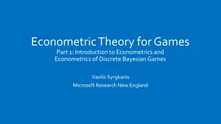
Figure 2.15 : (a) High Spin and (b) Low spin complexes of Cobalt (III) 2.1.4 High spin and low spin octahedral complexes w.r.t. Co (III). Cobalt ion ( Co3+) ground state = 3 d6 4s0 In this case, large 0 causes the low spin configuration t62g(no unpaired electrons ) while a small 0 causes the high spin configuration : t42g e2g ( four unpaired electrons ) Cobalt (Z = 27) atom ground state = 3 d 7 4 s 2 Figure 2.15 : (a) High Spin and (b) Low spin complexes of Cobalt (III) Refer to table 2.4 given below for energetics of complex formation Table 2.4 High and Low spin complexes Table 2.4 High and Low spin complexes
2.1.5Crystal Field stabilization energy (CFSE) : [ Ligand Field Stabilizing Energy (LFSE)] : The decrease in energy of metal ion caused by splitting of the energy levels is known as the crystal field stabilization energy. of the complex, in presence of the crystal field of ligands is termed as Ligand Field Stabilization Energy (LFSE) or Crystal Field Stabilization Energy (CFSE). This is the measure of intensity of electrostatic crystal field (ligand field) acting on the metal ion. It is expressed in terms of crystal field splitting parameter ( )(delta) or 10 Dq (ten dee que) . CFSE in Octahedral Complexes : When the electron distribution in the d orbital of the metal ion in an octahedral field is known, the corresponding crystal field stabilization energy can be calculated. As we have seen, for d1, d2, d3 and d8, d9, d10 configuration, the d-electrons can be distributed in one way only but for d4, d5, d6 and d7 configuration there can be two different spin states. respectively. As we have noted, the energy difference between the t2g and eg orbitals is defined as 0 or ( 10 Dq ) and there are three t2g and two eg orbitals ; the t2g orbitals lie 0 (6 Dq ) above the average. Therefore, in octahedral complexes, the filling of t2g orbitals decreases the energy of a complex that is it makes it more stable by 0.4 0 (-4 Dq), per electron. While filling the eg orbitals increases the energy of complex by +0.6 0 (+6 Dq) per electron. Thus the CFSE for the various electronic configurations, tx2g, eyeg, can be calculated by the general relation : orbitals respectively. In other words : The energy associated with the increased attraction leading to higher stability 0 (4 Dq) below the average energy and the eg orbitals lie CFSE (Oct) = [-0.4 x +0.6y ] 0 or = [-4 x + 6 y] Dq where x and y are the number of electrons in t2g and eg
When pairing occures, the electron experiences a strong coulombic repulsion. This is called the pairing energy P. Under such circumstances one cannot avoid the pairingpenalty but has to pay the price of pairing with the electron already present. The net CFSE is thus : Net CFSE = CFSE + zP where z is number of paired electrons and P is pairing energy. from the metal ion configurations d1 to d10. For Example : V4+, V3+ , V2+ having d1, d2 and d3 configurations, have their electrons in separate t2g orbitals with parallel spins, in accordance with Hund s rule. In their complex, the d-electrons occupy the lower t2g orbital and therefore, the complexes are stabilized by -0.4 0, -0.8 0 and -1.2 0 respectively. Theoretically, CFSE s can be evaluated for the different octahedral complexes,
For d4 case in weak field: where P > 0, ion say Cr2+, the electronic configuration is t32g e1g , the net CFSE is thus : CFSE = [3 x (-4 Dq) + (1 x 6Dq)] = -12 Dq + 6Dq = - 6 Dq or For d4 case, in strong field: where P < 0, the fourth electron enters the t2g orbitals and pair with one of the electron already there. Thus there are two unpaired and one paired electrons in t2g orbitals and the configuration is t42g e0g. CFSE = [3 x (-0.4 0) + (1 x 0.6 0)] = - 0.6 0 = -0.4 x 4 + 0.6 x 0 The CFSE will be then : CFSE = (-0.4 x + 0.6y ) 0 = -1.6 0, and Net CFSE = CFSE + zP = -1.6 0 + P 2P ). Similarly, for d5, having the configuration t32g e2g , CFSE is 0.0 and for t52g, CFSE is (-2.0 0 +
For d6, with t42g e2g configuration, CFSE is (-0.4 0 + P ) and with t62g e0g the net CFSE = (-2.4 0 + 3 P ). different angles. The study of CFSE helps to characterize any kind of complex to our almost satisfaction from electrons, magnetic moments, CFSE s weak field strong field cases, etc. for dn octahedral complex, where n= 1 to 10 is given in table 2.6 A summary of all the details of crystal field effects regarded to configurations number of unpaired
2.1.6 Merits and Demerits of CFT Following are the merits of CFT. Merits : 1. CFT accounts for a gradual and steady change in magnetic properties . e.g. high spin and low spin complexes are paramagnetic and diamagnetic respectively. 2. CFT give the information, regarding steriochemical properties (such as octahedral, tetrahedral, square planar, etc.) of complex. 3. CFT gives satisfactory explanation for colour and absorption spectra of transition metal complexes. 4. CFT is capable to account for kinetics and thermodynamic problems to a semiquantitative scale. 5. According to CFT bonding between metal and ligand is purely ionic. 6. When 0 is comparable to P, in some complexes, some change in temperature changes the magnetic moment. Thus CFT provides a theoretical basis to understand and to predict the variation in magnetic moments with temperature. CFT thus accounts for the detailed information of magnetic properties 7. CFT provides a ready interpretation for the phenomenon called as tetragonal distortion. 8. A satisfactory explanation is given by CFT for weak field ( high spin ) and strong field ( low spin ) complexes.
Limitations ( Demerits ) of CFT significant demerits i.e. serious limitations. Even though CFT is far superior to VBT and is crowned by specific merits, it is not free from 1. CFT assumes the bonding between metal and ligand to be purely ionic. It cannot account even a partial covalent bonding in complex formation. But there are some experimental evidences for both ionic and covalent bonding s in metal complexes. 2. CFT gives total emphasis on metal ion d-orbitals only. It does not give any thought to the ligand orbitals or the other orbitals such as s- and p- of the metal ion. Therefore, the properties dependent upon the ligand orbitals and the interactions thereof with metal orbitals cannot be explained by CFT. 3. CFT cannot explain satisfactorily the relative strength of ligands. 4. CFT cannot take into account the possibility of multiple bonding (pi bonding) in metal complexes.. 5. CFT cannot account for charge transfer spectra of complexes. See fig.2.10 . Inspite of the above drawbacks, CFT has had an enormous influence on inorganic chemistry because of its simplicity. It is in practice for last fifty years or so.
2 2. .2 2 MOLECULAR MOLECULAR ORBITAL 2.3.1.Introduction. Molecular orbital theory treats the whole molecule as a single polycentric nucleus. It tries to construct a system of molecular orbitals, characterized by a set of quantum numbers, in the same fashion as the atomic orbitals is treated in an atom. The molecular orbitals are constructed by the combination of atomic orbitals on metal ion and the ligands by the LCAO method and bonding comes into play in the complex compounds. Basis : The molecular orbital theory makes use of the same orbitals of the central metal ion as does the VBT viz. 3d, 4s and 4p. In addition, for construction of octahedral complexes, the theory makes use of the available orbitals of the co- ordinated ligands. Thus for the construction of MOs in an octahedral complex, total of fifteen AOs, nine from metal ion and six from six ligands are to be accounted for. In the formation of octahedral complex, it is first necessary to find out the suitable orbitals for LCAO, w.r.t. their energy, symmetry and extent of orbital overlap: On symmetry grounds, the nine significant AOs from metal atom are classified into four categories : 1. a1g : Non-degenerate or singly degenerate, totally symmetric, a single orbital having the full symmetry about n-fold axis i.e. 4s orbital. 2. eg : Doubly degenerate, two orbitals (dx2 y2 and dz2) of two fold symmetry, just symmetrically equivalent, differing in orientation only. 3. t1u : Triply degenerate (4px, 4py and 4pz), three orbitals of one fold symmetry, just equivalent in symmetry but differ in orientation only. 4. t2g : Triply degenerate set of three equivalent orbitals, (dxy, dyz and dzx) of two fold symmetry, differ only in spatial orientation. ORBITAL THEORY THEORY (MOT) (MOT)
Basic Assumptions of MOT : applied to the octahedral complexes may be presented as follows for ready reference : (i) MOT assumes bonding between metal ion and ligands to be purely ionic, purely covalent and all possible intermediate cases also. (ii) Out of nine AOs from the valence shell of metal ion : (a) Six orbitals viz. dx2+ y2, dz2, s, px, py and pz having lobes along the axes i.e. exactly in the directions of approaching ligands, cause head-on collision. Hence they are suitable for s-bonding. (b) The remaining three orbitals viz. dxy, dyz and dzx, having lobes between the fixes and hence between the ligands, are suitable for pi bonding only. (iii) Each ligand possesses at least one s-atomic orbital for bonding with the metal ion. (iv) The six ligands with six available s-AOs combine or mix together to form a new set of six AOs called Ligand Symmetry Orbitals (LSOs) or the Ligand Group' Orbitals (LGOs), perfectly suitable for LCAO. (v) Each metal ion-orbital combines with a LGO of matching (a) symmetry, (1)) energy and (b) geometry to form a bonding and an antibonding molecular orbital. (vi) All electrons are filled into MOs according to Aufbau principle. (vii) In addition to a bonding, Ti bonding can also occur if the ligands possess it orbitals to overlap with the matching symmetry it orbitals from metal ion. Refer to Fig. 2.15 to Fig. 2.18 for clear understanding. A brief summary of the important assumptions or salient features of MOT as
2.2.2. MOT of octahedral complexes with sigma bonding such as [Ti(H2O)6]3+,[CoF6]3 , [Co(NH3)6]3+ : By collecting theoretical information from the above discussion, MOT may be applied to construct MO energy level diagrams for some of the regular, simple, octahedral complexes like [Ti(H2O)6]3+, [Co(NH3)6]3+ and [CoF6]3 and [Ni(NH3)6]2+. From the molecular orbital correlation diagrams, octahedral complexes can be characterised qualitatively to our utmost satisfaction. 1. Hexa-aqua-titanium (III) ion, [Ti(H2O3)6]3+; d1 complex : Titanium (Z = 22) : Ground State Atom = [Ar] 4S2 3d2 Titanium Ion, Ti3+ : Ground State Ion = [Ar] 4s0 3d1 In [Ti(OH2)6]3+ ion, there are 13 electrons; 12 coming from six water molecules and one from Ti3+ ion. The MO energy level diagram for this complex may be constructed as shown in Fig. 2.22. The 13 electrons may be distributed according to the aufbau principle. The 12 electrons from ligands will occupy the low energy bonding MOs in the order a1g, t1u, and eg. The last electron, coming from Ti3+ ion, will then occupy the higher energy orbital i.e. one of the tn2g MO. Thus there Li only one unpaired electron in [Ti(H2O)6]3+ which accounts for its weak paramagnetic character. The transition of a single electron from tn2g MO to eg* MO (eg* tn2g) is responsible for giving a single broad absorption at 500 nm in UV-visible absorption spectrum of [Ti(H2O)6]3+ (Fig. 2.19). The frequency of absorption (20300 cm 1) corresponds to yellow-green and blue radiations and hence the complex is violet. This is the same observation as encountered earlier according to CFT. The HOMOs (Highest Occupied Molecular Orbitals) are the three tn2g orbitals. They are largely confined to the Ti3+ ion and their energy is same as those of the t2g orbitals of Ti3+ free ion, and contains its single electron . Fig. 2.19 : Qualitative Energy Level Diagram of [Ti(H2O)6]3+ ion
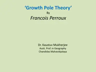
2. Hexafluorocobaltate ion (CoF6)3 : d6, High Spin Complex : Cobalt Atom (Z = 27) [Ar] 4s2 3d7 Cobalt Ion : Co3+ [Ar] 4s0 3d6 In the complex ion, [CoF6]3 there are 18 electrons, 12 of which are offered by six fluoride ions and 6 are from 3d orbitals of Co3+ ion. A qualitative energy level MO diagram for the complex may be pictured as shown in Fig. 2.20 (a). Out of 18 electrons, 12 are accommodated in the lower six a- bonding MOs: a1g , t1u, and eg. From the remaining six electrons, n four are placed in three non-bonding (tn2g) MOs while two are placed in the two antibonding (eg*) orbitals. As the energies of the 2p-orbitals on F are much lower, spectroscopic measurements show that Do (the gap between tn2g and eg* MOs - is 13000 cm 3) is much less than that of pairing energy, P(21,000 cm 1); (i.e. Do < < P). Therefore, the electrons try to remain unpaired as much as possible, both in tn2g and eg* orbitals, leading to (tn2g) (eg*) 2 configuration. Hund's rule is obeyed. The smaller value of Do is attributed to lesser extent of interaction (overlap) between eg orbitals of Co3+ and 6F . According to MO approach, the presence of two electrons in eg* orbitals effectively cancel out the contribution of two electrons in the bonding eg orbitals and hence weakens the Co-F bonds in the complex. [CoF6]3 is therefore a labile complex. Thus [CoF6]3 have four unpaired electrons and is a high spin complex. It is strongly paramagnetic complex. It is the case of weak ligand field. CFT also gives parallel explanation for [CoF6]3 ion. The HOMOs are eg eg* orbitals which are singly occupied, while a1g* is LUMO. The octahedral crystal field splitting parameter Do in this complex is the size gap between tn2g and eg* HOMOs. Fig. 2.20 : The MO Diagrams of High-spin [CoF6]3
3. Hexa-ammine cobalt(III) ion, [Co(NH3)6]3+ : d6 Low Spin Complex Cobalt Atom (Z 27) Cobalt Ion (Co3+ In the complex ion [Co(NH3)6]3+, there are 18 electrons; 12 from six ammonias and 6 from Co3+ ion. A qualitative energy level MO diagram for this complex is presented in Fig. 2.20 (b). Out of 18 electrons from the valence shell of Co3+ and 6 NH3 ligands, 12 electrons from the six ligands are accommodated in the low lying 6- bonding MOs : a1g, t1u, and eg. This accounts for the bond order six for the complex. The remaining six electrons from metal ion Co3+ are then accommodated in the three non-bonding orbitals (tn2g) as shown in the diagram. Thus the metal ion electrons contribute nothing to the bonding. The antibonding MOs are all empty. It is observed that the energy jump Do is 23000 cm 1 while energy of pairing P is 21000 cm 1. Because Do > P, all the six non-bonding d- electrons of Co3+ ion, are paired in the complex, giving the configuration (tn2g) 6(eg*)0. Thus Hund's rule is disobeyed. According to MOT this behaviour is attributed to the covalent bonding due to the greater orbital-overlap between eg of metal and eg of ligands producing a stronger covalent bond between metal and ligand in [Co(NH3)6]3+. The complex is diamagnetic as all the electrons are paired. It is an example of low-spin or spin-paired complex. The complex is expected to be coloured since promotion of electrons from the non-bonding (tn2g) MOs to the antibonding eg* MOs is rather feasible. Here blue light is absorbed, hence it appears pink or orange in solution. Similar explanation is sought by CFT where higher Do value is attributed to the strong field of NH3. The Do in this complex is the HOMO-LUMO separation. HOMOs are non-bonding completely full tn2g MOs whereas LUMOs are completely empty antibonding eg* MOs. Thus [CoF6]3 is high spin, highly paramagnetic complex whereas [Co(NH3)6]3+ is low spin, diamagnetic complex. An equivalent account may be provided to complexes like [FeF6]3 and (Fe(CN)6]3 , [CoF3(H2O)3] and [Co(CN)6]3 which are high spin and low spin respectively. [Ar] 4s2 3d2 [Ar] 4s0 3d6 Electronic transitions from HOMO to LUMO or the higher antibonding MOs lead to colour and spectra for the complex Fig. 2.20 : The MO Diagrams of Low- spin [Co(NH3)6]3+ complexes
3. Hexa-ammine cobalt(III) ion, [Co(NH3)6]3+ : d6 Low Spin Complex Cobalt Atom (Z 27) [Ar] 4s2 3d2 Cobalt Ion (Co3+ In the complex ion [Co(NH3)6]3+, there are 18 electrons; 12 from six ammonias and 6 from Co3+ ion. A qualitative energy level MO diagram for this complex is presented in Fig. 2.20 (b). Out of 18 electrons from the valence shell of Co3+ and 6 NH3 ligands, 12 electrons from the six ligands are accommodated in the low lying 6-bonding MOs : a1g, t1u, and eg. This accounts for the bond order six for the complex. The remaining six electrons from metal ion Co3+ are then accommodated in the three non-bonding orbitals (tn2g) as shown in the diagram. Thus the metal ion electrons contribute nothing to the bonding. The antibonding MOs are all empty. It is observed that the energy jump Do is 23000 cm 1 while energy of pairing P is 21000 cm 1. Because Do > P, all the six non-bonding d-electrons of Co3+ ion, are paired in the complex, giving the configuration (tn2g) 6(eg*)0. Thus Hund's rule is disobeyed. According to MOT this behaviour is attributed to the covalent bonding due to the greater orbital-overlap between eg of metal and eg of ligands producing a stronger covalent bond between metal and ligand in [Co(NH3)6]3+. Note : The greater the overlap of eg orbitals of the metal with ligand orbital, the greater will be the splitting between tn2g and eg* and higher will be Do. The complex is diamagnetic as all the electrons are paired. It is an example of low-spin or spin-paired complex. The complex is expected to be coloured since promotion of electrons from the non-bonding (tn2g) MOs to the antibonding eg* MOs is rather feasible. Here blue light is absorbed, hence it appears pink or orange in solution. Similar explanation is sought by CFT where higher Do value is attributed to the strong field of NH3. The Do in this complex is the HOMO-LUMO separation. HOMOs are non-bonding completely full tn2g MOs whereas LUMOs are completely empty antibonding eg* MOs. Thus [CoF6]3 is high spin, highly paramagnetic complex whereas [Co(NH3)6]3+ is low spin, diamagnetic complex. An equivalent account may be provided to complexes like [FeF6]3 and (Fe(CN)6]3 , [CoF3(H2O)3] and [Co(CN)6]3 which are high spin and low spin respectively. [Ar] 4s0 3d6
4. Hexa-ammine Nickel (II) ion, [Ni(NH3)2]2+ : d8 complex : Nickel Atom (Z = 28) : [Ar] 4s2 3d8 Nickel Ion, Ni2+ : [Ar] 4s0 3d8 In the complex ion (Ni [NH3)6]2+, there are 20 electrons, 8 from 3d of Ni2+ ion and 12 offered by six ammonias. A qualitative energy level MO diagram for the complex [Ni(NH3)6]2+ may be pictured as shown in Fig. 2.21. Ni2+ and 6NH3 ligands, 12 electrons of six ligands are accommodated in the law lying six, bonding MOs a1g, t1u and eg. Six electrons occupy non bonding tn2g MOs. Two electrons which are left get accommodated in the two anti-bonding eg* MOs and remain unpaired. The complex is, therefore, paramagnetic. The presence of two electrons in eg* effectively cancel out the contribution of two electrons in bonding eg orbitals, and thus weakens the Ni-NH3 bonds in [Ni(NH3)6)]2+. The complex is therefore, a labile complex. The smaller Do (10,800 cm 1) between eg* and tn2g is attributed to poor interaction between eg orbitals of Ni2+ and those of LGOs from 6NH3. The HOMOs are eg* while a*1g is LUMO. Electronic transitions from HOMOs to LUMO or higher antibonding MOs lead to colour and spectra of the complex. Out of 20 electrons from the valence shell of Fig. 2.21 : Qualitative energy level diagram of [Ni(NH3)6]2+
Merits of MOT : the most correct and general is the MO approach to account for complex ion formation. 1. MOT accounts for all possible interactions between metal orbitals and the ligand orbitals. i.e. all degrees of overlap, including the electrostatic situation, are thoughtfully considered. 2. It successfully accounts the presence of n bonding and the increased stability of complexes especially with strong field ligands. 3. MOT can provide satisfactory explanation to the charge transfer spectra on the basis of availability of antibonding MOs for electronic transitions originating from t2g and the lower bonding levels. See Fig. 2.24. 4. It gives satisfactory information for high spin and low spin complexes, their different magnetic" moments and variations, in Do values. 5. It takes into account all possible orbitals of metal ion as well as of ligands for construction of MO energy level diagram i.e. s, p, d etc. of metal ion and s as well as rc orbitals on ligands. 6. MOT can successfully account for the stability, geometry and relative energies of different structures of metal complexes, unlike VBT or CFT. Hence, it is quite complete theory. 7. It accounts for cloud expanding effect. Of all the approaches, the most versatile, most sophisticated and perhaps
Demerits of MOT : hence it suffers from certain serious drawbacks. The molecular orbital theory, although potentially the most powerful, is not free from defects. Its demerits are : 1. In principle MOT is the most accurate theory, but since calculations and predictions are made only with great difficulty, it is not that easy to apply rigorously to the different problems. 2. Many approximations are to be made in its quantitative application to multi-electron multi-atom complex ion systems. 3. Unfortunately, being the most complicated, MOT does not lend itself to pictorial representation of bonding. 4. Many times its qualitative application, to the simple regular octahedral complexes without it bonding, is only taken into consideration, on the basis of LCAO approximation. In short, MOT is too general to apply. Any theory of bonding in complexes is essentially a partial approach;
Q. 1 Choose the correct alternative and rewrite the sentence : 1. MOT is the most sophisticated, the most general, the most accurate and correspond the most theory. (a) simple (b) qualitative (c) veg (d) difficult 2. According to MOT bonding between metal and ligand may be (a) ionic (b) covalent (c) semi polar (d) any type 3. Complex having CN = 6 has shape. (a) T.B.P. (b) Square planar (c) tetrahedral (d) octahedral 4. Octahedral distortion is caused for metal complex having system. (a) d0, d1, d2 (b) d3, d5, d8 (c) d1, d3, d5 (d) d4, d7, d9 5. [CoCl6]2 complex has symmetry (a) octahedral (b) hexagonal (c) distorted tetrahedral 6. Tetragonal complexes have additional stabilization over complexes. (a) square planar (b) tetrahedral (c) trigonal pyramidal (d) regular octahedral 7. According to MOT, [Ni[NH3)6]2+ is paramagnetic with unpaired electrons. (a) zero (b) one (c) three (d) two (d)tetragonal
9. 10. Molecular orbital theory was proposed by........... (a) Hund, Pauli (c) Heitler, London, Slatter 11. During formation of a complex each approaching ligand should have at least (a) one bond pair (b)two lone pair (c) one unpaired electron (d) one lone pair 12. CFT was proposed by (a) H. Bethe and Weisackar (b) H. Bethe and Hahn (c) H. Bethe and Lewis (d) H. Bethe and J. Van Vleck 13. Ligands are considered as (a) charged species (b) charge group (c) point group (d) point charges 14. During formation of octahedral complex ligands interact with metal (a) either along axes or between axes (b)between axes (c) neither along axes nor between axes (d) along axes 15. According to John and Tellar , in non linear molecule distortion occurs due to (a) lower the symmetry (b) remove the degeneracy (c) lower the energy (d) all of these 16. Increase in CFSE the stability of complexes. (a) first increases ,then decreases (b) decreases (c) non of these (d) increases 17. In spin paired complexes almost all electrons are (a) unpaired (b)non of these (c) either paired or unpaired (d paired In octahedral complexes each t2g electrons is stabilized by (a) 6Dq (c) +6Dq (b) +4Dq (d) 4Dq (b) Hund, Pauli and Slatter (d)Hund, Malliken, Huckel
Q.2. Answer in one sentence. 1. Define the crystal field splitting . 2. Daw a neat and labelled diagram for CF-splitting in octahedral complex. 3. Daw a neat and labelled diagram for CF-splitting in tetrahedral complex. 4. Daw a neat and labelled diagram for CF-splitting in square planer complex. 5. Daw a neat and labelled diagram for CF-splitting in tetragonal complex. 6. Mention the factors affecting the magnitude of crystal field splitting. 7. Define weak field ligand. 8. Define strong field ligand. 9. Define CFSE. 10. Give the Fajan Tsuchida spectrochemical series for ligands 11. Sketch the shapes of t2g orbitals 12. Sketch the shapes of eg orbitals 13. Sketch the shapes of t1u orbitals 14. Who proposed CFT for transition metal complexes 15. Who proposed CFT for transition metal complexes 16. Sketch the shape of a1g bonding and antibonding molecular orbitals 17. Define Aufbaus principle 18. who developed the MOT for complexes?
Q.2. Short Answer Type Questions : 1. MO diagram for octahedral complex. 2. MOT and [Ti(OH2)6]3+. 3. MOT for [Ni(NH3)6]2+. 4. Write a short note on optical isomerism. 5. Give one coordination isomerism. 6. Draw the MO diagram for [Ti(H2O)6]3+ 7. Draw the MO diagram for [Ni(NH3)6]2+ 8. Draw the MO diagram for [Co(NH3)6]3+ 9.Give a brief account of CFT w. r. t. An octahedral complex. Bonding in 10. What is crystal field stabilization energy ? How will you calculate it for a strong field and weak field complex with d6 configuration in terms of 10 Dq value or 0 value. example of 11. What are the factors affecting the magnitude of crystal field splitting? 12. State and explain the high spin and low spin octahedral complexes of Co(III). 13.Describe in brief with suitable example, Jahn -Teller distortion. 14.Draw the MO diagram for an octahedral complex [Ti (H2O)6]3+ and explain its colour and spectra .
Q.2 Long answer questions. .Draw MO diagram for[Co (NH3)6]3+ and[Co F6]-3.Why [Co (NH3)6]3+ is diamagnetic while[Co F6]-3 is paramagnetic? Draw MO diagram for[Co (NH3)6]3+ and[Co F6]-3.Why [Co (NH3)6]3+ is low spin complex while[Co F6]-3 is high spin complex? 1. Draw the MO diagram for an octahedral complex[CoF6]3+ and explain its colour spectra and magnetic characters . 2. Draw MO diagram for[Co (NH3)6]3+ and explain its magnetic characters 3. 4. Draw the qualitative MO diagram for Co (III) complex, without the bonding and interpret it. 5. Explain in brief merits and demerits of MOT.

 :")


 Basic Assumptions of CFT")


 High Spin and (b) Low spin complexes of")
 :")


 of CFT")


3− − : d6, High")
 ion, [Co(NH3)6]3+ : d6 Low Spin")
 ion, [Co(NH3)6]3+ : d6 Low Spin")
 ion, [Ni(NH3)2]2+ : d8 complex :")