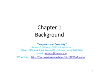
Analog-to-Digital Converter
This content delves into the fundamental concepts and practical applications of analog-to-digital conversion (ADC). Learn how ADC enables the transformation of analog signals into digital data for processing, explore the importance of sampling intervals, and grasp the significance of digital signal representation. Gain insights into the role of ADC in converting continuous analog phenomena into manageable digital values, and discover the functionalities of DAC (digital-to-analog converter).

Download Presentation

Please find below an Image/Link to download the presentation.
The content on the website is provided AS IS for your information and personal use only. It may not be sold, licensed, or shared on other websites without obtaining consent from the author.If you encounter any issues during the download, it is possible that the publisher has removed the file from their server.
You are allowed to download the files provided on this website for personal or commercial use, subject to the condition that they are used lawfully. All files are the property of their respective owners.
The content on the website is provided AS IS for your information and personal use only. It may not be sold, licensed, or shared on other websites without obtaining consent from the author.
E N D
Presentation Transcript
CS4101 Analog-to-Digital Converter Prof. Chung-Ta King Department of Computer Science National Tsing Hua University, Taiwan Materials from MSP430 Microcontroller Basics, John H. Davies, Newnes, 2008 National Tsing Hua University
Recall the Container Thermometer Container thermometer: monitor the temperature of the interior of a container Monitor the temperature every 5 minutes Flash LED alarm at 1 Hz If the temperature rises above a threshold, flash the LED alarm at 3 Hz and notify backend server If the temperature drops below a threshold, return the LED alarm to normal and notify the server Need to know the temperature! 1 National Tsing Hua University
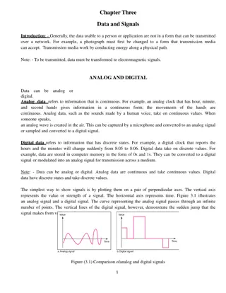
Digitizing Temperature Temperature is a nature phenomena, whose value varies continuously To make it feasible for computer to handle, we need to convert it into a digital number To transform an analog signal into a digital number, the analog-to-digital converter (ADC) samples the input at fixed interval and do the conversion Analog signal Digital signal 2 National Tsing Hua University
So Far, We Have Learned ADC Clock System IO Timer System 3 National Tsing Hua University
Outline Introduction to analog-to-digital conversion ADC of MSP430 Sample code of using ADC10 in MSP430 4 National Tsing Hua University
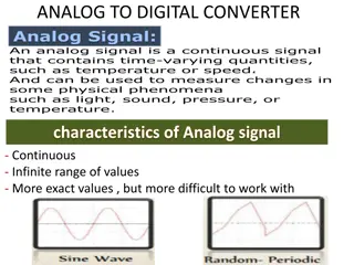
Analog Signals A signal representing continuous things, e.g. Fluctuations in air pressure (i.e. sound) strike the diaphragm of a microphone, which causes corresponding fluctuations in the voltage or current in an electric circuit The voltage or current signal is an "analog" of the sound voltage strength time time 5 National Tsing Hua University
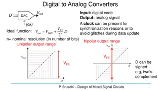
Analog-to-Digital Conversion (ADC) ADC: convert an analog signal, e.g., a voltage V, into a binary value that the processor can handle The input V(t) is a continuous function, i.e., V can take any value within a permitted range and can change in any way as a function of time t The output V[n] is a sequence of binary values, each has a fixed number of bits and can represent only a finite number of values Typically input is sampled regularly at intervals of T, so the continuous nature of time has also been lost Of course, we also have DAC (digital-to-analog converter)! 6 National Tsing Hua University
Analog-to-Digital Conversion Digital representation of an analog signal Continuous time Continuous values Discrete time Discrete values 7 National Tsing Hua University
Sampling in Time The value of the analog signal is measured at certain intervals in time. Each measurement is referred to as a sample A series of snapshots 8 National Tsing Hua University
Terminologies in Sampling Sampling rate: How often analog signal is measured (samples per second, Hz), e.g. 44,100 Hz? Sampling resolution: Number of bits to represent each sample ( sample word length, bit depth ), e.g. 16 bit Analog Input 4 samples/cycle 16 samples/cycle 8 samples/cycle 9 National Tsing Hua University
Encoding of Discrete Signals If we use N bits to encode the magnitude of one of the discrete-time samples, we can capture 2N possible values 10 National Tsing Hua University
Sampling Rate and Encoding Bits 1-bit 3-bit 11 National Tsing Hua University
Outline Introduction to analog-to-digital conversion ADC of MSP430 Sample code of using ADC10 in MSP430 12 National Tsing Hua University
Requirements of MSP430 for ADC Provide continuous sampling of multiple analog inputs and store sampled data ADC10AE0 INCH in ADC10CTL1 13 National Tsing Hua University
Requirements of MSP430 for ADC Provide continuous sampling of multiple analog inputs and store sampled data SHS, ADC10SSEL, CONSEQ in ADC10CTL1 14 National Tsing Hua University
Requirements of MSP430 for ADC Provide continuous sampling of multiple analog inputs and store sampled data Interrupt CPU on every word sampled from ADC Use software (ISR run by the CPU) to move data from ADC (ADC10MEM) to memory 15 National Tsing Hua University
Requirements of MSP430 for ADC Provide continuous sampling of multiple analog inputs and store sampled data Use hardware (Data Transfer Controller, DTC) to move data from ADC to memory DMA Interrupt CPU when block transfer is completed 16 National Tsing Hua University
ADC in MSP430 MSP430 may contain one or more converters: Comparator: Compare the voltages on its two input terminals and return 0 or 1, e.g., Comparator_A+ Successive-approximation ADC: Use binary search to determine the closest digital representation of the input signal, e.g., ADC10 and ADC12 to give 10 and 12 bits of output Sigma-delta ADC: A more complicated ADC that gives higher resolution (more bits) but at a slower speed, e.g., SD16 and SD16_A, both of which give a 16-bit output 17 National Tsing Hua University
Simplified Block Diagram of ADC10 Voltage reference Clock sources Conversion trigger 18 National Tsing Hua University
Main Components of ADC10 Analog inputs: Some are from internal, e.g. temperature, and some are from external, e.g. A0, A1, , A7 19 National Tsing Hua University
Main Components of ADC10 Sample-and-Hold circuit: Vout = Vin when Vsample = 1 Vin Vout SAR (Successive-Approximation Register): 10-bit Result written to ADC10MEM and raising ADC10IFG 20 National Tsing Hua University
Successive-Approximation ADC Generate internal analog signal VD/A by DAC Compare VD/A with input signal Vin Modify VD/A by D0D1D2 DN-1 until closest possible value to Vin is reached Vin S&H Logic D0 D1 DN-1 VD/A DAC Vref Dr.-Ing. Frank Sill, Department of Electrical Engineering, Federal University of Minas Gerais, Brazil 21 National Tsing Hua University
Successive-Approximation ADC 111 111 110 110 7 8 VD/A V ref 101 101 V in 100 100 4 8 V 011 ref 011 010 010 V 001 ref 001 8 000 1. 2. 3. final result Iterations P. Fischer, VLSI-Design - ADC und DAC, Uni Mannheim, 2005 22 National Tsing Hua University
Main Components of ADC10 Built-in voltage reference: Setting REFON in ADC10CTL0 register to 1 enables the internal reference Two selectable voltage levels: 2.5 V and 1.5 V Setting REF2_5V in ADC10CTL0 to 1 selects 2.5 V as the internal reference, otherwise 1.5 V After voltage reference is turned on, we must wait about 30 s for it to settle 23 National Tsing Hua University
Main Components of ADC10 Reference voltage: 1.5V or 2.5V ADC10MEM: 10-bit output of ADC conversion 0x3FF for 1.5V or 2.5V 24 National Tsing Hua University
Main Components of ADC10 Triggering of sample-and-hold circuit: By ADC10SC bit in ADC10CTL0 register, which can be set (and is thus triggered) by software, or OUTx from Timer0_A: for periodic sampling Capture/Compare Block 2 of Timer0_A 25 National Tsing Hua University
Data Transfer Controller (DTC) Transfer conversion results from ADC10MEM to other on-chip memory locations Each load of ADC10MEM triggers a data transfer until a set amount During each DTC transfer, CPU is halted 1.5V or 2.5V or Reference Input channel ADC10MEM 26 National Tsing Hua University
ADC10 Interrupts One interrupt and one interrupt vector When DTC is not used (ADC10DTC1 = 0), ADC10IFG is set when conversion results are loaded into ADC10MEM When DTC is used (ADC10DTC1 > 0), ADC10IFG is set when a block transfer completes If both ADC10IE and GIE bits are set, then ADC10IFG generates an interrupt request ADC10IFG is automatically reset when interrupt request is serviced, or it may be reset by software 27 National Tsing Hua University
Enabling Sampling and Conversion 28 National Tsing Hua University
Steps for Single Conversion (1) Configure ADC10, including the ADC10ON bit to enable the module. The ENC bit must be clear so that most bits in ADC10CTL0 and ADC10CTL1 can be changed. (2) Set the ENC bit to enable a conversion. This cannot be done if the module is being configured in (1). (3) Trigger the conversion. This is done either by setting the ADC10SC bit or by an edge from Timer_A. ADC10ON, ENC, ADC10SC are all in control register ADC10CTL0 29 National Tsing Hua University
ADC10 Registers Register Type Register Short Form Addr. Initial State ADC10 input enable register 0 ADC10AE0 Read/write 04Ah Reset with POR ADC10 input enable register 1 ADC10AE1 Read/write 04Bh Reset with POR ADC10 control register 0 ADC10CTL0 Read/write 01B0h Reset with POR Reset with POR ADC10 control register 1 ADC10CTL1 Read/write 01B2h ADC10 memory ADC10MEM Read 01B4h Unchanged ADC10 data transfer control register 0 ADC10DTC0 Where the converted 10-bit digital value is saved Read/write 048h Reset with POR ADC10 data transfer control register 1 ADC10DTC1 Read/write 049h Reset with POR ADC10 data transfer start address ADC10SA Read/write 01BCh 0200h with POR 30 National Tsing Hua University
ADC10CTL0 ideal for the temperature sensor ideal for the temperature sensor 31 National Tsing Hua University
ADC10CTL0 contd ADC10CTL0 = SREF_2 + ADC10SHT_1; // Reference range & SH time 32 National Tsing Hua University
ADC10CTL1 33 National Tsing Hua University
ADC10CTL1 contd ADC10CTL1 = INCH_10 + ADC10DIV_0; // Temp Sensor ADC10CLK 34 National Tsing Hua University
Outline Introduction to analog-to-digital conversion ADC of MSP430 Sample code of using ADC10 in MSP430 35 National Tsing Hua University
Sample Code 1 for ADC10 Repetitive single conversion: Repetitively perform single samples on A1 (pin P1.1) with reference to Vcc If A1 > 0.5*Vcc, P1.0 set, else reset. Set ADC10SC to start sample and conversion But ADC10SC automatically cleared at end of conversion. Enable the next conversion in ISR of ADC10 and iterate 36 National Tsing Hua University
Sample Code 1 for ADC10 void main(void) { WDTCTL = WDTPW + WDTHOLD; // Stop WDT // H&S time 16x, interrupt enabled ADC10CTL0 = ADC10SHT_2 + ADC10ON + ADC10IE; ADC10CTL1 = INCH_1; // Input from A1 ADC10AE0 |= 0x02; // Enable pin A1 for analog in P1DIR |= 0x01; // Set P1.0 to output ADC10CTL0 |= ENC + ADC10SC; // Start sampling for (;;) { } } #pragma vector=ADC10_VECTOR __interrupt void ADC10_ISR(void) { if (ADC10MEM < 0x1FF) P1OUT &= ~0x01; else P1OUT |= 0x01; ADC10CTL0 |= ENC + ADC10SC; // enable sampling } 37 National Tsing Hua University
Sample Code 2 for ADC10 Continuous sampling driven by Timer0_A3 A1 is sampled 16/second with reference to 1.5V, where ACLK runs at 32 KHz driven by an external crystal (2048 ACLK cycles give 1/16 second (ACLK/2048)) If A1 > 0.5V, P1.0 is set, else reset. Timer0_A3 is run in up mode with CCR0 defining the sampling period (2048 cycles) Use CCR1 to automatically trigger ADC10 conversion 38 National Tsing Hua University
Sample Code 2 for ADC10 #include msp430.h int i=1; void main(void) { WDTCTL = WDTPW + WDTHOLD; // Stop WDT // TA1 trigger sample start ADC10CTL1 = SHS_1 + CONSEQ_2 + INCH_1; ADC10CTL0 = SREF_1 + ADC10SHT_2 + REFON + ADC10ON + ADC10IE; __enable_interrupt(); // Enable interrupts TA0CCR0 = 30; // Delay for Volt Ref to settle TA0CCTL0 |= CCIE; // Compare-mode interrupt TA0CTL = TASSEL_2 + MC_1; // SMCLK, Up mode while(i); // Wait for settle TA0CCTL0 &= ~CCIE; // Disable timer Interrupt __disable_interrupt(); How to break? 39 National Tsing Hua University
Sample Code 2 for ADC10 ADC10CTL0 |= ENC; // ADC10 Enable ADC10AE0 |= 0x02; // P1.1 ADC10 option select P1DIR |= 0x01; // Set P1.0 output TA0CCR0 = 2048-1; // Sampling period TA0CCTL1 = OUTMOD_3; // TACCR1 set/reset TA0CCR1 = 2046; // TACCR1 OUT1 on time TA0CTL = TASSEL_1 + MC_1; // ACLK, up mode while(1); } Timer0_A CCR1 out mode 3: The output (OUT1) is set when the timer counts to the TA0CCR1 value and is reset when the timer counts to the TA0CCR0 value. 40 National Tsing Hua University
Sample Code 2 for ADC10 // ADC10 interrupt service routine #pragma vector=ADC10_VECTOR __interrupt void ADC10_ISR(void){ if (ADC10MEM < 0x155) // ADC10MEM = A1 > 0.5V? P1OUT &= ~0x01; // Clear P1.0 LED off else P1OUT |= 0x01; // Set P1.0 LED on } #pragma vector=TIMERA0_VECTOR __interrupt void ta0_isr(void){ TA0CTL = 0; i = 0; } Break the while loop in main() that waits for the internal voltage reference to settle 41 National Tsing Hua University
Summary ADC: analog-to-digital conversion DAC: digital-to-analog conversion Conversions will necessarily introduce errors. Important to understand constraints and limitations ADC10 in MSP430 Convert an analog signal into 10-bit digitals Registers associated with ADC10 Sample program of ADC10 Single conversion Continuous conversion driven by Timer_A 42 National Tsing Hua University


")


")