Analysing Epitaxial Layers and Diffraction in Materials Science
Explore the intricate world of diffraction with X-rays, high-energy electrons, and neutrons, studying properties, geometrical principles, and intensities. Delve into kinematical and dynamical theories, experimental techniques, and advanced methodologies like X-ray diffractometry and high-resolution setups. Gain insights into epitaxial layers - from perfectly matched to strained and partially relaxed ones, revealing details through diffraction analysis. Unravel the complexities of substrates, interplanar spacings, and relaxation phenomena in crystalline structures. Experience a visual journey through high-quality images capturing diffraction patterns and lattice descriptions.

Uploaded on | 0 Views
Download Presentation

Please find below an Image/Link to download the presentation.
The content on the website is provided AS IS for your information and personal use only. It may not be sold, licensed, or shared on other websites without obtaining consent from the author. If you encounter any issues during the download, it is possible that the publisher has removed the file from their server.
You are allowed to download the files provided on this website for personal or commercial use, subject to the condition that they are used lawfully. All files are the property of their respective owners.
The content on the website is provided AS IS for your information and personal use only. It may not be sold, licensed, or shared on other websites without obtaining consent from the author.
E N D
Presentation Transcript
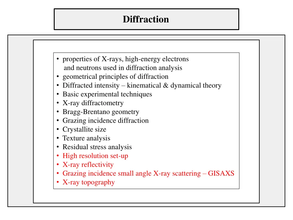
Diffraction properties of X-rays, high-energy electrons and neutrons used in diffraction analysis geometrical principles of diffraction Diffracted intensity kinematical & dynamical theory Basic experimental techniques X-ray diffractometry Bragg-Brentano geometry Grazing incidence diffraction Crystallite size Texture analysis Residual stress analysis High resolution set-up X-ray reflectivity Grazing incidence small angle X-ray scattering GISAXS X-ray topography
High resolution diffraction epitaxial layers completely relaxed layer Strained layer perfectly matched to the substrate partially relaxed layer with misfit dislocations
Diffraction from the substrate with epi-layer Intensity layer peak substrate peak layer substrate Different interplanar spacing dhkl of planes parallel to the sample surface causes that the diffraction from the substrate and the layer occurs at different Bragg angles. For high quality epitaxial layers this difference can be as small as 0.01 . Further improvements of the quality of the primary beam are necessary.
Description of the epitaxial layer in RS reciprocal lattice perfectly matched strained layer substrate
Description of the epitaxial layer in RS reciprocal lattice completely relaxed layer substrate
Description of the epitaxial layer in RS reciprocal lattice partially relaxed layer substrate determination of the composition and the degree of relaxation requires to measure at least one symmetric and one asymmetric diffraction
Relaxation line of epitaxial layer in RS substrate diffraction spot h, k non-zero diffraction spot of completely relaxed layer relaxation line diffraction spot of strained layer no relaxation towards the origin of RS
Presentation of InxAl1-xN in reciprocal space l [0001] relaxation line of AlN h [1120] diffraction 1124 of GaN aspect ratio c/a = f(x) c/a (c/a)GaN
Presentation of InxAl1-xN in reciprocal space l [0001] relaxation line of AlN 4.4 R = 0 > 0 R = 1 0.96 0.92 h [1120] 1.04 diffraction 1124 of GaN < 0 3.6 R = 1 R = 0 3.2
Why do we need high resolution diffraction? epitaxial layers similar lattice parameters of the substrate and the layer(s) the difference may be spectral width of the radiation the precision of the measurement is given by beam divergence Cu K 1 K 2separation parameters of standard diffractometry slit collimator Goebel mirror elimination of K 2and decreasing of the angular divergence is necessary
Limitation of standard diffractometry h s intensity profile d divergence s = 0.1 mm h = 0.1 mm d = 200 mm monochromators d ~ 100 m
Monochromator principle < focus of X-ray tube
Non-dispersive arrangement < focus of X-ray tube all wavelengths are diffracted at the same orientation
Dispersive arrangement < focus of X-ray tube each wavelength is diffracted at different orientation
Monochromatization of the primary beam Bartels monochromator two Ge channel cut crystals with 220 symmetrical diffraction outgoing beam incoming beam
Analyzer crystal - Pathfinder detector Bartels sample monochromator Pathfinder Focus of X-ray tube slit collimator or triple bounce Ge channel cut crystal Monochromator in the diffracted beam analyzer excellent angular resolution of the diffracted beam misorientation of mosaic blocks and strain can be separated
Epitaxial layer GaAs/Ga1-xInxP diffraction 004 7 10 standard diffraction 6 10 Bartels monochromator 5 Bartels + Pathfinder 10 Intensity [cps] 4 10 3 10 2 10 1 10 0 10 65.6 65.8 66.0 2 [ ] 66.2 66.4
Si/AlN/3x AlGaN/GaN diffraction 0002 Bartels Bartels + Pathfinder 105 104 Intensity [cps] 103 102 101 100 15 16 17 18 19 20 [ ]
Accessible region of the reciprocal space (RS) Ewald construction sample origin of RS
Scans in RS symmetric -2 scan 2
Scans in RS asymmetric offset -2 scan 2
Scans in RS scan 2
Scans in RS detector scan (GI diffraction) 2
Scans in RS accessible lattice points in coplanar geometry symmetric /2 or 2 / scan forbidden area forbidden area
Scans in RS series of scans for varying 2 angle RS mapping transformation into the rectangular coordinates by an appropriate software is necessary
Reciprocal space angular vs. linear scans curved streets advisable for poetic walking but complicated orientation straight streets monotonous walking but easy orientation
Scans in RS linear scans PC control of up-to-date diffractometers h l
Scans in RS direct mapping of rectangular area additional numerical processing of the data is not necessary
Cross section of RS for GaN lattice symmetric and asymmetric angular scans 3% 5% 11-24+ 11-24- 0004 0002 11-22- 45% 22%
Failure of asymmetric angular scan of Si/AlN/3x AlGaN/GaN Bartels Bartels + Pathfinder 105 104 Intensity [cps] 5 103 10 GaN 11-24 102 101 100 4 15 16 17 18 19 20 10 [ ] 11-24 grazing input Intensity [cps] 11-24 grazing output 3 10 maxima of AlN and AlGaN layers are not detected 2 10 1 10 0 10 98.0 100.0 102.0 2 [ ] 104.0 106.0
Solution use of linear scans 105 (a) 104 Intensity [cps] 103 102 101 100 3.95 4.00 4.05 4.10 4.15 4.20 l [ ] 103 h coordinate: -1.0000 (GaN) -1.00780 (AlGaN) -1.0161 (AlGaN) -1.0198 (AlGaN) -1.021 (AlN) (b) 102 Intensity [cps] 0004 101 11-24 100 -1.04 -1.02 h coordinate [ ] -1.00 -0.98 -0.96
Reconstruction of RS 11-24 0004 l scan path of 2 / scan Stacking in real space AlN GaN AlGaN-80 AlGaN-50 AlGaN-20 AlGaN-20 AlGaN-50 AlGaN-80 GaN h scans AlN silicon (111) Reciprocal coordinates of the layer points can be determined and the composition and the lateral strain can be calculated
RS map confirmation of the results Advantage complete information on the epitaxial system Disadvantage measuring of RS map requires ~102times more time than the linear scans
HR diffraction layers with high perfection GaAs/AlAs/GaAs/InGaAs/AlGaAs/GaAs ~11 nm In0.22Ga0.78As GaAs ~330 nm Al0.98Ga0.02As fine oscillations due to interaction of amplitudes from different layers with very close lattice parameters
HR diffraction layers with high perfection 107 l scan across 004 l scan across 224 GaAs 106 AlAs Intensity [cps] 105 InGaAs 104 103 102 101 100 3.85 reciprocal coordinate l [ - ] 3.90 3.95 4.00 4.05 4.10 similar intensity distribution around 004 and 224 no relaxation of the layers!
Resolution in the reciprocal space divergence of the monochromator acceptance of the analyzer spectral width of K 1 2 Resolution power
Double axis vs. Triple axis diffractometry TAXRD DAXRD acceptance of the analyzer divergence of the monochromator angular acceptance of the detector - entrance slit
Lattice tilt or lattice strain? DAXRD angular resolution of the diffracted beam is not sufficient!
DAXRD /2 scan strain tilt
TAXRD /2 scan strain tilt off-set /2 scan symmetric /2 scan symmetric /2 scan
X-ray reflectivity optical measurement in the range of X-rays can be applied to crystalline as well as amorphous thin layers contrast in electron density is important! symmetrical 2 / scan in the angular range 0 ~ 10 of 2
X-ray reflectivity reflection of X-rays from smooth surface Calculated amplitude Arfor different absorption, Si= 7.56 10-6
Parameters of reflectivity curve simulation procedure model with free parameters Analysis of parameters of layers and interfaces 1e8 1e7 density of the layer(s) attenuation of oscillation 1e6 1e5 critical angle Log (Counts) thickness of the layer(s) 1e4 1000 frequency of 100 thickness (Kiessig) fringes roughnesses of the surface and interfaces 0 1 2 3 4 5 6 7 2-Theta - Scale Pt-Si_ref - File: Pt-Si_ref.raw - Type: 2Th/Th locked - Start: 0.0000 - End: 7.0000 - Step: 0.0100 - Step time: 1. s - Temp.: 25 C (Room) - Time Started: 4 s - 2-Theta: 0.0000 - Theta: 0.0000 - Chi Operations: Import
X-ray reflectivity example single layer Si/Pt LEPTOS software (Bruker)
X-ray reflectivity example multilayer Si/(2nm Ni80Fe20/1.6 nm Au/0.8nm Co/1.6nm Au)x10 0 10 measurement -2 10 fit Reflectivity 5s 15s -4 10 KEC 1s 1s -6 10 -8 10 0 2 4 6 (deg) measured and simulated by M. Jergel IP SAS
Grazing Incidence Small Angle X-ray Scattering GISAXS symmetric 2 / scan (reflectivity) scan rocking curve rocking curves at small angles diffuse scattering
Grazing Incidence Small Angle Scattering - GISAXS measuring the intensity out-of standard diffraction plane GISAXS 2D detector necessary!
Grazing Incidence Small Angle Scattering - GISAXS Characterization of self-organization in thin films on the nanoscale, quantum dot arrays, instabilities during growth, nanostructures R. Lazzari, in: J. Daillant, A. Gibaud: X-ray and Neutron Reflectivity
GISAXS experimental requirements High intensity laboratory sources are insufficient Possible solution synchrotron radiation Microfocus air-cooled Source (metaljet Incoatec) IP SAS Low divergency of primary beam in both directions, elimination of axial divergence Montel optics two crossed Goebel mirrors IP SAS Area (2D) detector
GISAXS example (a) TEM image of 0.9 nm thick Pd/MgO (100) deposit. (b) Experimental and simulated GISAXS pattern. Particle model truncated sphere. R. Lazzari, in: J. Daillant, A. Gibaud: X-ray and Neutron Reflectivity


")