Bandwidth Signaling for EDMG
Explore the proposal by Laurent Cariou and team from Intel regarding bandwidth and primary channel indication in Extended Data Modulation Group (EDMG). The presentation outlines definitions and signaling methods, emphasizing channelization, signal transmission for channel bonding, and primary channel selection rules. Additionally, the proposal addresses channel configurations, frequency considerations, and the implications of channel overlap for regulatory compliance in different regions.

Download Presentation

Please find below an Image/Link to download the presentation.
The content on the website is provided AS IS for your information and personal use only. It may not be sold, licensed, or shared on other websites without obtaining consent from the author. If you encounter any issues during the download, it is possible that the publisher has removed the file from their server.
You are allowed to download the files provided on this website for personal or commercial use, subject to the condition that they are used lawfully. All files are the property of their respective owners.
The content on the website is provided AS IS for your information and personal use only. It may not be sold, licensed, or shared on other websites without obtaining consent from the author.
E N D
Presentation Transcript
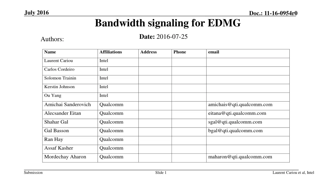
July 2016 Doc.: 11-16-0954r0 Bandwidth signaling for EDMG Date: 2016-07-25 Authors: Name Affiliations Address Phone email Laurent Cariou Intel Carlos Cordeiro Intel Solomon Trainin Intel Kerstin Johnson Intel Ou Yang Intel Amichai Sanderovich Qualcomm amichais@qti.qualcomm.com Alecsander Eitan Qualcomm eitana@qti.qualcomm.com Shahar Gal Qualcomm sgal@qti.qualcomm.com Gal Basson Qualcomm bgal@qti.qualcomm.com Ran Hay Qualcomm Assaf Kasher Qualcomm Mordechay Aharon Qualcomm maharon@qti.qualcomm.com Submission Slide 1 Laurent Cariou et al, Intel
July 2016 Doc.: 11-16-0954r0 Content Part 1: Define channelization and BW/primary channel indication in EDMG header A Part 2: Define how to signal BW in RTS/CTS for channel bonding operation Submission Slide 2 Laurent Cariou et al, Intel
July 2016 Doc.: 11-16-0954r0 PART 1 Submission Slide 3 Laurent Cariou et al, Intel
July 2016 Doc.: 11-16-0954r0 Bandwidth and primary channel indication The SFD specifies that: An EDMG STA shall be able to determine the primary channel and occupied bandwidth from any EDMG PPDU it receives. The EDMG-HEADER-A field has: A bandwidth (BW) field that defines the bandwidth of the PPDU and the occupied channels A Primary Channel Number field that indicates which channel is the primary channel We propose to define more precisely those fields We start by clarifying channelization Submission Slide 4 Laurent Cariou et al, Intel
July 2016 Doc.: 11-16-0954r0 Channelization We propose: To define channelization for up to 6 2.16 GHz channels, which accounts for the accepted expansion of the 60 GHz band in the US Ensure that we can further define up to 8 channels We propose to change the channelization from non- overlapping to overlapping Otherwise channel bonding cannot be used in some regulatory domains (e.g., China) Will need to be signaled in the BW field Will need to define some rules for primary channel selection Channel BW Channel BW #1 #2 #3 #4 #5 #6 2.16GHz #9 #11 #13 4.32GHz #10 #12 #19 #17 6.48GHz #18 #20 #25 #26 8.64GHz #27 we consider only 2.16GHz+2.16GHz and 4.32GHz+4.32GHz mode for channel aggregation Not support for 4.32+2.16, .. Frequency (GHz) Submission Slide 5 Laurent Cariou et al, Intel
July 2016 Doc.: 11-16-0954r0 Channelization section Add the following equations: to describe the relationship between center frequency and channel numbers for 2.16, 4.32, 6.48, 8.64GHz. We don t assign channel numbers to an aggregation of non-contiguous channels Those are identified by two 2.16GHz channel segments bandwidth 2.16GHz 4.32GHz 6.48GHz 8.64GHz Channel center frequency calcuation Channel center frequency = Channel starting frequency + Channel spacing Channel number Channel center frequency = Channel starting frequency + (Channel spacing/2) (Channel number mod 8)+1.08GHz Channel center frequency = Channel starting frequency + (Channel spacing/3) (Channel number mod 16)+2.16GHz Channel center frequency = Channel starting frequency + (Channel spacing/4) (Channel number mod 24)+3.24GHz Submission Slide 6 Laurent Cariou et al, Intel
July 2016 Doc.: 11-16-0954r0 Channelization Channel starting frequency Channel spacing Channel center frequency Channel BW Channel BW channel 56.16 56.16 56.16 56.16 56.16 56.16 56.16 56.16 56.16 56.16 56.16 56.16 56.16 56.16 56.16 56.16 56.16 56.16 2160 2160 2160 2160 2160 2160 4320 4320 4320 4320 4320 6480 6480 6480 6480 8640 8640 8640 1 2 3 4 5 6 9 58.32 60.48 62.64 64.80 66.96 69.12 59.40 61.56 63.72 65.88 68.04 60.48 62.64 64.80 66.96 61.56 63.72 65.88 #1 #2 #3 #4 #5 #6 2.16GHz #9 #11 #13 4.32GHz #10 #12 10 11 12 13 17 18 19 20 25 26 27 #19 #17 6.48GHz #18 #20 #25 #26 8.64GHz #27 Frequency (GHz) Submission Slide 7 Laurent Cariou et al, Intel
July 2016 Doc.: 11-16-0954r0 Channelization annex E Change Table E-1 as follows 34 35 36 37 180 181 182 183 56.16 56.16 56.16 56.16 Reserved 2160 4320 6480 8640 Reserved 1-6 9-13 17-20 25-27 Reserved - - - - - - 3538-127 Reserved Reserved Reserved Submission Slide 8 Laurent Cariou et al, Intel
July 2016 Doc.: 11-16-0954r0 BW and primary channel fields The SFD specifies 2 fields, one for BW, and one for primary channel. Channel BW Channel BW #1 #2 #3 #4 #5 #6 2.16GHz We propose to add one bit Channel aggregation field to differentiate between bonded channels and aggregated channels Set to zero for channel bonding or single 2.16GHz Set to one for channel aggregation #9 #11 #13 4.32GHz #10 #12 #19 #17 6.48GHz #18 #20 #25 #26 8.64GHz We propose that the BW , channel bonding and primary channel fields are designed the same way for inclusion in EDMG-Header-A field and in control trailer #27 Frequency (GHz) Submission Slide 9 Laurent Cariou et al, Intel
July 2016 Doc.: 11-16-0954r0 Primary channel indication We consider 6 channels And ensure that we can scale up to 8 channels We propose to use 3 bits to encode the 3 LSBs of the (channel number -1) corresponding to the primary channel channel 1 channel 2 channel 3 channel 4 channel 5 channel 6 Primary channel index 1 2 3 4 5 6 Submission Slide 10 Laurent Cariou et al, Intel
July 2016 Doc.: 11-16-0954r0 Bandwidth field Channel BW Channel BW Proposal: simple 8 bits bitmap The BW field is 8 bits long: Bit 1-8 corresponds to channel 1-8 For each channel, the corresponding bit is set to 1 if modulated and to 0 if not modulated #1 #2 #3 #4 #5 #6 2.16GHz #9 #11 #13 4.32GHz #10 #12 #19 #17 6.48GHz #18 #20 #25 #26 8.64GHz #27 With this solution, we can: Scale up to 8 channels if more channels become available Encode all the bandwidth combinations that we are interesting in Frequency (GHz) Submission Slide 11 Laurent Cariou et al, Intel
July 2016 Doc.: 11-16-0954r0 PART 2 Submission Slide 12 Laurent Cariou et al, Intel
July 2016 Doc.: 11-16-0954r0 Motivation Channel bonding is a pivotal feature for 802.11ay. Duplicated RTS/CTS must carry the bandwidth information for efficient channel bonding operation. Control trailer is a good approach for enabling EDMG information to be carried on control PHY messages, including RTS/CTS The bandwidth field in the control trailer should then be the same as in EDMA-A header (8 bit bitmap) Submission Slide 13 Laurent Cariou et al, Intel
July 2016 Doc.: 11-16-0954r0 Motivation [cont.] Control trailer requires additional 2us overhead. It increases RTS/CTS overheads by 12%. =2usec/(14usec + 3usec) Dense deployments are more sensitive to this overhead, since the RTS/CTS is sent multiple times. DMG devices can not read this information. There is no software upgrade that will enable DMG STAs to read the control trailer. Only new hardware can do that. Submission Slide 14 Laurent Cariou et al, Intel
July 2016 Doc.: 11-16-0954r0 Proposal We propose to signal a compressed BW field using bits 22-23 in DMG Control Header and the scrambler seed This compressed BW field only signals the main channel bonding modes Side benefit: Current SFD defined that bits 22-23 of DMG control header signals both EDMG-Header-A and control trailer [3.1.1 and 6.2.3.2.2]. This is ambiguous. Our proposal correct that ambiguity Submission Slide 15 Laurent Cariou et al, Intel
July 2016 Doc.: 11-16-0954r0 Proposal When reserved bits 22-23 are set to 1, use the following codes to signal the following in the scrambler seed: [0 0 X X]: indicates the presence of a control trailer [0 1 X X]: indicates the presence of an EDMG-Header A [1 B1 B2 B3]: in case of RTS/CTS, B1-B3 are used for compressed bandwidth signaling. For other frames, B1-B3 are reserved Compressed bandwidth is signaled by the scrambler seed. Define only commonly used options for this compressed signaling. Suggested usage of a 3 bits bandwidth signaling field is relegated to the backup. Use control trailer on other DMG control mode frames and/or to signal additional bandwidth combinations Submission Slide 16 Laurent Cariou et al, Intel
July 2016 Doc.: 11-16-0954r0 Straw poll #1 Do you agree to change channelization section 6.2.4 of the SFD to include overlapping channels, with the following figure and with the changes proposed in slide 4 and 6. Channel BW Channel BW #1 #2 #3 #4 #5 #6 2.16GHz #9 #11 #13 4.32GHz #10 #12 #19 #17 6.48GHz #18 #20 #25 #26 8.64GHz #27 Frequency (GHz) Submission Slide 17 Laurent Cariou et al, Intel
July 2016 Doc.: 11-16-0954r0 Straw poll #2 Do you agree to add to the SFD: 1 bit channel aggregation field is added in EDMG-Header-A for SU and MU PPDU Set to zero for channel bonding or single 2.16GHz channel Set to one for channel aggregation the BW field is 8 bits long: Bit 1-8 corresponds to channel 1-8 For each channel, the corresponding bit is set to 1 if modulated and to 0 if not modulated The spec shall only allow the following combinations for channel aggregation: 2.16GHz + 2.16GHz 4.32GHz + 4.32GHz the Primary Channel field is 3 bits long and contains the 3 LSBs of (channel number-1) corresponding to the primary channel of the BSS. the format of the BW and Primary Channel fields are the same for inclusion in the EDMG-Header- A field and in the control trailer. Submission Slide 18 Laurent Cariou et al, Intel
July 2016 Doc.: 11-16-0954r0 Straw poll #3 Do you agree to add to the SFD the following and update section 6.2.3.2.2: When reserved bits 22-23 are set to 1 in the PHY header of a Control mode PPDU, the Scrambler Initialization field shall be formatted as follows [X means that the value for this bit is reserved]: [0 0 X X]: indicates the presence of a control trailer (see 3.1.1) [0 1 X X]: indicates the presence of an EDMG-Header A. [1 B1 B2 B3]: in case of RTS/CTS, B1-B3 are used for bandwidth signaling. For other frames, B1-B2 are reserved." Y/N/A Submission Slide 19 Laurent Cariou et al, Intel
July 2016 Doc.: 11-16-0954r0 Annex Submission Slide 20 Laurent Cariou et al, Intel
July 2016 Doc.: 11-16-0954r0 Suggested options In case 3 bits are used to signal BW in scrambler seed Enumeration of [3 bits] Signaled CH_BANDWIDTH CH1+CH2 CH2+CH3 CH1+CH2+CH3 CH2+CH3+CH4 CH3+CH4+CH5 CH1+CH2+CH3+CH4 CH2+CH3+CH4+CH5 CH3+CH4+CH5+CH6 0 1 2 3 4 5 6 7 CH3+CH4 CH4+CH5 CH4+CH5+CH6 CH5+CH6 Bonded/Aggregated Bonded/Aggregated Bonded Bonded Bonded Bonded Bonded Bonded Submission Slide 21 Laurent Cariou et al, Intel