Bistable Circuits and Their Applications
Learn about bistable circuits, which are digital circuits with two inputs and stable output states. Explore the basics, timing diagrams, and specific ICs like 4043 and 4013 used in constructing bistable circuits. Discover how bistable circuits can be utilized in various applications.

Download Presentation

Please find below an Image/Link to download the presentation.
The content on the website is provided AS IS for your information and personal use only. It may not be sold, licensed, or shared on other websites without obtaining consent from the author. If you encounter any issues during the download, it is possible that the publisher has removed the file from their server.
You are allowed to download the files provided on this website for personal or commercial use, subject to the condition that they are used lawfully. All files are the property of their respective owners.
The content on the website is provided AS IS for your information and personal use only. It may not be sold, licensed, or shared on other websites without obtaining consent from the author.
E N D
Presentation Transcript
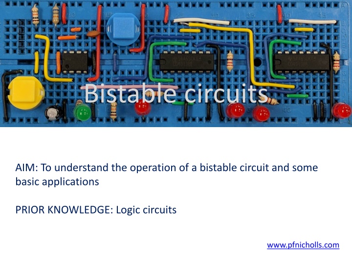
Bistable circuits AIM: To understand the operation of a bistable circuit and some basic applications PRIOR KNOWLEDGE: Logic circuits www.pfnicholls.com
Introduction A Bistable is a digital circuit that has two inputs and a digital output. The SET input makes the output Logic 1 (HIGH) and the output will stay in this state indefinitely until forced to change. The RESET input makes the output Logic 0 (LOW) and the output will also stay in this state indefinitely until forced to change. The output of a Bistable circuit is stable in both states - it can remain as either Logic 1 or Logic 0 indefinitely until either the SET or RESET initiate a change of state. The name means that the circuit has two (bi) stable states.
Bistable basics A Bistable has two inputs called Set (S) and Reset (R). The output is called Q. There is often a second output which is the opposite of Q or, in logic terms, NOT Q or Q-Bar Set and Reset are usually LOW and must go HIGH to change the output. When SET goes HIGH, Q goes HIGH. Q changes on the rising edge of the SET input.
Timing diagram The first time SET (Red line) goes HIGH it makes the OUTPUT (Green line) go HIGH. Making the SET go HIGH again has no further effect - the OUTPUT stays HIGH. Making the RESET (Blue line) go HIGH makes the OUTPUT go LOW. Making the RESET go HIGH again has no further effect - the OUTPUT stays LOW.
4043 Bistable The 4043 IC contains four separate bistables each with a SET, a RESET and a single Q output. The 4043 IC has an ENABLE input. The Enable controls the tristate output of all four bistables together. When the ENABLE is HIGH, the outputs of each bistable are either HIGH or LOW as expected. When the enable is LOW the outputs are not connected to the bistables and simply float to any value.
4043 Test Circuit A simple test circuit is shown with the ENABLE connected directly to 9V making it permanently HIGH Two inputs are provided by push buttons
4013 as a Bistable A bistable can easily be built from a 4013 D-type flip-flop IC. The 4013 has a SET and RESET as expected and also has outputs Q and Q-Bar making it preferable to the 4043 IC in some cases. There are two other inputs called CLOCK (Ck) and DATA (D) that are not used and must be connected to ground The 4013 IC contains two separate flip-flops and so can be used to provide two separate bistables that operate independently.
4013 Test Circuit A simple bistable circuit using a 4013 D-type flip-flop with Clock and Data connected to ground and two output LEDs.
Simple Logic Bistable At the heart of a bistable circuit are two inverting logic gates. The output of each logic gate is connected to the input of the other logic gate. Such a circuit has two states where it is stable. The most basic logic gate bistable is made from two NOT gates as shown in the diagram. Situation 1: Assume A = 0 and therefore B = 1. B = 1 and therefore C = 0 ... but C is connected to A and so A = 0 as required. Situation 2: Assume A = 1 and therefore B = 0. B = 0 and therefore C = 1 ... but C is connected to A and so A = 1 as required. Whether A = 0 or A = 1, the circuit works (is stable) in both cases.
NOR Gate Bistable Consider the function of the NOR gate. When A = 0 (as shown circled in red) then the NOR gate acts like a NOT gate with B and Q being opposite in both cases. Therefore the NOR gate can replace the NOT gate in the simple logic bistable. However, when A = 1, Q = 0 irrespective of the state of B therefore A is acting like a RESET. This is an excellent bistable circuit. When SET and RESET are both LOW the NOR gates act as NOT gates and the bistable has two stable states. SET and RESET can safely be made HIGH as they are not directly connected to the output of the NOR gates - they are only inputs.
NAND Gate Bistable Consider the function of the NAND gate. When A = 1 (as shown circled in red) then the NAND gate acts like a NOT gate with B and Q being opposite in both cases. Therefore the NAND gate can replace the NOT gate in the simple logic bistable if A is held HIGH. However, when A = 0, Q = 1 irrespective of the state of B therefore A is acting like a SET. Note that in this case the SET and RESET inputs are normally HIGH and must go LOW to cause a change to happen - this type of logic is called "NAND gate logic" or "NAND logic".
Summary A bistable is a circuit with two stable output states. The output can be HIGH and it will stay HIGH or the output can be LOW and it will stay LOW The SET input makes the output HIGH The RESET input makes the output LOW Bistable integrated circuits include the 4043 and the 4013 A bistable is made from a pair of interconnected NOT gates It is better to use NOR gates or NAND gates instead of NOT gates as these circuits can be SET and RESET An input that is normally LOW is referred to as NOR gate logic and an input that is normally HIGH is NAND gate logic
Questions 1. How many stable states does a bistable have? 2. What are the inputs to a bistable circuit called? 3. Where might a bistable circuit be useful? 4. What logic gates can be used to make the most basic bistable? 5. What does NOR gate logic mean? 6. What does NAND gate logic mean?
Answers 1. Two it is stable with the output HIGH or LOW 2. SET and RESET 3. In an alarm circuit where one input turns the alarm on but a different input is required to turn the alarm off 4. A pair of NOT gates 5. NOR gate logic is when the normal state of an input is LOW and the input goes HIGH to force a change 6. NAND gate logic is when the normal state of an input is HIGH and the input goes LOW to force a change