Building 2m Roll-up J-Poles: Transmission Lines, Impedance Matching, and More
In this workshop, we will delve into the world of building 2m Roll-up J-Poles. Topics covered include understanding transmission lines (balanced and unbalanced), impedance matching techniques, velocity factor, and tools for simplifying complex calculations. Explore the versatility of Roll-up J-Poles for various bands and discover useful websites for mathematical computations. Learn about coaxial cable attenuation and power handling considerations, as well as the differences between 50-ohm and 75-ohm cables. Equip yourself with the knowledge to optimize your antenna system for enhanced performance.

Uploaded on Mar 05, 2025 | 1 Views
Download Presentation

Please find below an Image/Link to download the presentation.
The content on the website is provided AS IS for your information and personal use only. It may not be sold, licensed, or shared on other websites without obtaining consent from the author.If you encounter any issues during the download, it is possible that the publisher has removed the file from their server.
You are allowed to download the files provided on this website for personal or commercial use, subject to the condition that they are used lawfully. All files are the property of their respective owners.
The content on the website is provided AS IS for your information and personal use only. It may not be sold, licensed, or shared on other websites without obtaining consent from the author.
E N D
Presentation Transcript
2m Roll-up J-Pole Dallas N4DDM GARS Workshop - November 16, 2021 M0UKD s Slim Jim and J-Pole Calculator
2m Roll-up J-Pole What I ll touch on for this Workshop Before we start building I would like to teach a few things about Transmission Lines Transmission lines; balanced (twin lead, window line, ladder line), unbalanced (coax) Impedance matching using a wave matching stub Impedance matching using non-50-ohm wave transmission line When life gives you lemons, you make lemonade Velocity Factor, what it is and how it affects the math Websites that do the math so you don t need your slide ruler, calculator, or aspirin Dallas twist to the Roll-up J-Pole that I don t see anywhere
2m Roll-up J-Pole Roll-up J-Poles can be made for other bands 70cm 420-450 435MHz 1.25m 219-225 222MHz 2m 144-148 146MHz What we will be building 6m 50-54 52MHz 10m 28-29.7 28.85MHz or just the Tech SSB 28.3-28.5 28.4MHz 12m 15m 17m 20m? Air Band Frequencies, 118-137MHz, 127.5MHz VHF Marine Band, Ch16 156.800MHz NOAA Weather 7 channels, Ch 3 162.475MHz My demo from scrap Window Line FRS/GRMS 22 channels, 465.1315MHz
2m Roll-up J-Pole Websites used for most of our heavy math skills M0UKD s Slim Jim and J Pole Calculator https://m0ukd.com/calculators/slim-jim-and-j-pole-calculator/ Google; convert cm to inches https://www.google.com/search?q=convert+cm+to+inches Times Microwave - Coax Cable Loss Calculator https://www.timesmicrowave.com/Calculator?
2m Roll-up J-Pole Times Microwave Systems - Coaxial Cable Attenuation Calculator On the next slide I ll use the Times Microwave Calculator to show losses based on coax Set the cable type; RG-6, RG-59, RG-58, RG-8x Set the frequency to 146 MHz... Plug in the cable length in feet, 20 feet for this antenna Calculate and compare the results with other cables Know your losses before you part with your time and money Every gain on an antenna system is a two-fer Less loss on transmit AND Less loss on receive
2m Roll-up J-Pole 50-ohm vs 75-ohm cable Times Microwave Systems - Coaxial Cable Attenuation & Power Handling Calculator RG-58 50-ohm 20 feet at 146MHz Cable Vg 66.0% Cable loss 5.5dB/100ft - Max Cable Assembly Insertion Loss 1.2dB https://www.timesmicrowave.com/Calculator?Product=RG-58&RunLength=20&Frequency=146 RG-59 75-ohm 20 feet at 146MHz Cable Vg 66.0% Cable loss 4.1dB/100ft - Max Cable Assembly Insertion Loss 0.9dB https://www.timesmicrowave.com/Calculator?Product=RG-59&RunLength=20&Frequency=146
2m Roll-up J-Pole 50-ohm vs 75-ohm cable Times Microwave Systems - Coaxial Cable Attenuation & Power Handling Calculator RG-8X 50-ohm 20 feet at 146MHz Cable Vg 66.0% Cable loss 4.5dB/100ft - Max Cable Assembly Insertion Loss 1.0dB https://www.timesmicrowave.com/Calculator?Product=RG-59&RunLength=20&Frequency=146 RG-6 75-ohm 20 feet at 146MHz Cable Vg 66.0% Cable loss 3.3dB/100ft - Max Cable Assembly Insertion Loss 0.7dB https://www.timesmicrowave.com/Calculator?Product=RG-6&RunLength=20&Frequency=146
2m Roll-up J-Pole WHAT!!! 75-ohm cable has less loss than 50-ohm The story I heard was the Navy wanted the best coax Coax is a compromise, you can get low loss OR high power, not BOTH 35-ohm cable can handle more power but doesn t like high SWR... 75-ohm cable has less loss, that s why the cable TV industry uses it... 50-ohm is somewhere in the middle
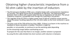
The Quarter Wave Stub Magical Properties The short at the bottom reflects as an open at the top Easy to visualize as we can see the short and the open What s hard to visualize is that at some point between the open and short there is a 50-ohm impedance point The J-Pole calculator does the math to find that 50-ohm impedance point In this case it is used to match the coax impedance to the open end of the wave antenna This is just like using a balun to match 50-ohm cable to the end of a EFHW HF antenna
Maybe a future Workshop I ve been told that the top section can be a 5/8s wave for a little more gain https://en.wikipedia.org/wiki/J-pole_antenna
2m Roll-up J-Pole The Half Wave Stub - We only need this if we are going to use 75-ohm cable Different Magical Properties Becomes a 1:1 impedance transformer Meaning it matches the input impedance to the output impedance So your 50-ohm radio sees the 50-ohm antenna (Wavelength / 2 ) x Velocity Factor We will use the J-Pole calculator but we will use the Vg factor for RG-59 which is 66% Belden 8241 RG-59/U Velocity Factor 66% https://catalog.belden.com/techdata/EN/8241_techdata.pdf 67.8cm = 26.69291 inches x 9 = 240.23619 inches = 20.0196825 feet Use an Antenna Analyzer or Vector Network Analyzer to trim your 20+ foot cable
2m Roll-up J-Pole Coax Balun What is a Coax Balun and why do we want/need one When you transition from unbalanced to balanced transmission line, current can run down the outer skin of the coax and radiate distorting the radiation pattern of your antenna Think of a nice beam pattern with great front to back ratio distorted by a vertical run of coax It can also put unwanted RF in your shack causing RF burns At 146MHz, 3-4 turns for coax should fix this It also lets you secure the coax to the base of the antenna so no stress is on the soldered connection.
2m Roll-up J-Pole To facilitate building the antennas I have construction tips On the demo antenna: See how to make the top and bottom shorts adjustable. This lets you tune the 50-ohm point by moving the bottom short Moving the top short adjust the antenna length On the 2x4 note the dimensions show where to mark your Window Line: Top and bottom shorts (Try to center them on a solid section of the Window Line) 50-ohm impedance point (Try to center this on an open section of the Window Line) Gap (Try to center this on a solid section of the Window Line OR on a small window) Leave room at the top and bottom to hang the antenna and mount the 3-turn coax balun
https://m0ukd.com/calculators/slim-jim-and-j-pole-calculator/https://m0ukd.com/calculators/slim-jim-and-j-pole-calculator/ = 56.61 ins = 18.62 ins = 1.85 ins = .83 ins
2m Roll-up J-Pole All About Circuits - College level info on and wave transmission lines Impedance Transformation - Chapter 14 - Transmission lines https://www.allaboutcircuits.com/textbook/alternating-current/chpt-14/impedance-transformation/ https://www.allaboutcircuits.com/textbook/alternating-current/chpt-14/standing-waves-and-resonance/
2m Roll-up J-Pole What I ll hope you took away from this Workshop When you see a J-Pole antenna you will see and know the parts that make it work wave radiating element matching network The 50-ohm impedance point Balun Transmission lines can do more than get your signal from your radio to your antenna Matching networks Filters
2m Roll-up J-Pole How to make your next J-Pole antenna better? How about making the top section wave for more gain? How about making it out of copper pipe? (also known as a Copper Cactus) How to add 3dB of, low cost, bi-directional amplification using passive components? That s 3dB gain on transmit and 3dB gain on receive Your 5 watt HT would have 10 watts of punch Your 50 watt radio would have 100 watts of punch How many of y all would like to build a J-Pole out of copper pipe? How many would like to build a collinear J-Pole with 3dB more gain?