CASE IH QUANTUM 80F Tractor Service Repair Manual Instant Download
CASE IH QUANTUM 80F Tractor Service Repair Manual Instant Download
Download Presentation

Please find below an Image/Link to download the presentation.
The content on the website is provided AS IS for your information and personal use only. It may not be sold, licensed, or shared on other websites without obtaining consent from the author. If you encounter any issues during the download, it is possible that the publisher has removed the file from their server.
You are allowed to download the files provided on this website for personal or commercial use, subject to the condition that they are used lawfully. All files are the property of their respective owners.
The content on the website is provided AS IS for your information and personal use only. It may not be sold, licensed, or shared on other websites without obtaining consent from the author.
E N D
Presentation Transcript
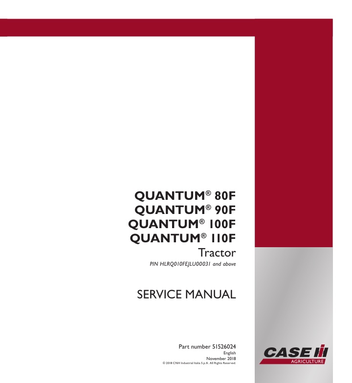
SERVICE MANUAL QUANTUM 80F QUANTUM 90F QUANTUM 100F QUANTUM 110F QUANTUM 80F QUANTUM 90F QUANTUM 100F QUANTUM 110F Tractor Tractor PIN HLRQ010FEJLU00031 and above SERVICE MANUAL 1/4 Part number 51526024 Part number 51526024 English November 2018 2018 CNH Industrial Italia S.p.A. All Rights Reserved.
Link Product / Engine Product Market Product Latin America Engine Quantum 100F With cab [HLRQ010FEJLU00031 - ] Quantum 100F With cab [HLRQ010FEJLU00031 - ] Quantum 100F Without cab [HLRQ010F*JLU***** - ] Quantum 100F Without cab [HLRQ010F*JLU***** - ] Quantum 110F With cab [HLRQ011FCHLU05201 - ] Quantum 110F With cab [HLRQ011FCHLU05201 - ] Quantum 110F Without cab [HLRQ011F*JLU***** - ] Quantum 110F Without cab [HLRQ011F*JLU***** - ] Quantum 80F With cab [HLRQ080FKHLU10308 - ] Quantum 80F With cab [HLRQ080FKHLU10308 - ] Quantum 80F Without cab [HLRQ080FJJLU00045 - ] Quantum 80F Without cab [HLRQ080FJJLU00045 - ] Quantum 90F With cab [HLRQ090FTHLU07802 - ] Quantum 90F With cab [HLRQ090FTHLU07802 - ] Quantum 90F Without cab [HLRQ090F*JLU***** - ] Quantum 90F Without cab [HLRQ090F*JLU***** - ] F5DFL413K*C001 Australia New Zealand F5DFL413K*C001 Australia New Zealand F5DFL413K*C001 Latin America F5DFL413K*C001 Latin America F5DFL413J*C002 Australia New Zealand F5DFL413J*C002 Latin America F5DFL413J*C002 Australia New Zealand F5DFL413J*C002 Australia New Zealand F5DFL413B*H001 Latin America F5DFL413B*H001 Latin America F5DFL413B*H001 Australia New Zealand F5DFL413B*H001 Australia New Zealand F5DFL413L*C001 Latin America F5DFL413L*C001 Australia New Zealand F5DFL413L*C001 Latin America F5DFL413L*C001 51526024 28/11/2018
Contents INTRODUCTION Engine....................................................................................... 10 [10.001] Engine and crankcase ............................................................. 10.1 [10.114] Pump drives ........................................................................ 10.2 [10.216] Fuel tanks .......................................................................... 10.3 [10.206] Fuel filters .......................................................................... 10.4 [10.202] Air cleaners and lines .............................................................. 10.5 [10.254] Intake and exhaust manifolds and muffler ......................................... 10.6 [10.501] Exhaust Gas Recirculation (EGR) exhaust treatment.............................. 10.7 [10.400] Engine cooling system ............................................................. 10.8 [10.414] Fan and drive ...................................................................... 10.9 [10.310] Aftercooler........................................................................ 10.10 [10.304] Engine lubrication system........................................................ 10.11 Clutch ....................................................................................... 18 [18.100] Clutch mechanical release control ................................................. 18.1 [18.104] Clutch hydraulic release control.................................................... 18.2 [18.110] Clutch and components ............................................................ 18.3 Transmission.............................................................................. 21 [21.114] Mechanical transmission ........................................................... 21.1 [21.130] Mechanical transmission external controls......................................... 21.2 [21.100] Mechanical transmission hydraulic components................................... 21.3 [21.140] Mechanical transmission internal components..................................... 21.4 [21.112] Power shuttle transmission......................................................... 21.5 [21.134] Power shuttle transmission external controls ...................................... 21.6 [21.104] Power shuttle transmission hydraulic components ................................ 21.7 [21.154] Power shuttle transmission internal components .................................. 21.8 [21.160] Creeper ............................................................................ 21.9 51526024 28/11/2018
https://www.ebooklibonline.com Hello dear friend! Thank you very much for reading. Enter the link into your browser. The full manual is available for immediate download. https://www.ebooklibonline.com
[21.162] Reverser ......................................................................... 21.10 [21.168] Hi-Lo unit......................................................................... 21.11 [21.109] Transmission cooler and lines.................................................... 21.12 [21.118] Transmission/Rear drive ......................................................... 21.13 [21.182] Differential........................................................................ 21.14 Four-Wheel Drive (4WD) system .................................................. 23 [23.202] Electro-hydraulic control ........................................................... 23.1 [23.304] Four-Wheel Drive (4WD) gearbox ................................................. 23.2 [23.314] Drive shaft.......................................................................... 23.3 Front axle system ....................................................................... 25 [25.100] Powered front axle ................................................................. 25.1 [25.102] Front bevel gear set and differential ............................................... 25.2 [25.108] Final drive hub, steering knuckles, and shafts ..................................... 25.3 [25.310] Final drives......................................................................... 25.4 [25.400] Non-powered front axle ............................................................ 25.5 Rear axle system........................................................................ 27 [27.100] Powered rear axle.................................................................. 27.1 [27.106] Rear bevel gear set and differential................................................ 27.2 [27.120] Planetary and final drives .......................................................... 27.3 [27.126] Spur gear and final drives.......................................................... 27.4 Power Take-Off (PTO)................................................................. 31 [31.101] Rear mechanical control ........................................................... 31.1 [31.142] Front Power Take-Off (PTO) control ............................................... 31.2 [31.146] Front Power Take-Off (PTO) ....................................................... 31.3 Brakes and controls .................................................................... 33 [33.202] Hydraulic service brakes ........................................................... 33.1 [33.110] Parking brake or parking lock ...................................................... 33.2 51526024 28/11/2018
[33.220] Trailer brake hydraulic control...................................................... 33.3 [33.204] Front axle brake.................................................................... 33.4 Hydraulic systems....................................................................... 35 [35.000] Hydraulic systems.................................................................. 35.1 [35.104] Fixed displacement pump.......................................................... 35.2 [35.204] Remote control valves ............................................................. 35.3 [35.100] Main lift system..................................................................... 35.4 [35.114] Three-point hitch control valve ..................................................... 35.5 [35.124] Three-point hitch hydraulic adjustment ............................................ 35.6 [35.160] Front hitch controls and lines ...................................................... 35.7 [35.162] Front hitch cylinders and lines ..................................................... 35.8 Hitches, drawbars, and implement couplings.................................. 37 [37.110] Rear three-point hitch .............................................................. 37.1 [37.120] Rear three-point hitch linkage...................................................... 37.2 [37.162] Front hitch.......................................................................... 37.3 [37.166] Front hitch linkage.................................................................. 37.4 Frames and ballasting................................................................. 39 [39.140] Ballasts and supports .............................................................. 39.1 Steering..................................................................................... 41 [41.101] Steering control .................................................................... 41.1 [41.200] Hydraulic control components...................................................... 41.2 Wheels...................................................................................... 44 [44.511] Front wheels........................................................................ 44.1 [44.520] Rear wheels........................................................................ 44.2 Cab climate control..................................................................... 50 [50.100] Heating............................................................................. 50.1 [50.104] Ventilation .......................................................................... 50.2 [50.200] Air conditioning..................................................................... 50.3 51526024 28/11/2018
[50.300] Cab pressurizing system........................................................... 50.4 Electrical systems....................................................................... 55 [55.100] Harnesses and connectors......................................................... 55.1 [55.525] Cab engine controls................................................................ 55.2 [55.015] Engine control system.............................................................. 55.3 [55.201] Engine starting system............................................................. 55.4 [55.301] Alternator........................................................................... 55.5 [55.302] Battery.............................................................................. 55.6 [55.011] Fuel tank system ................................................................... 55.7 [55.010] Fuel injection system............................................................... 55.8 [55.014] Engine intake and exhaust system................................................. 55.9 [55.989] Exhaust Gas Recirculation (EGR) electrical system ............................. 55.10 [55.640] Electronic modules............................................................... 55.11 [55.513] Cab transmission controls........................................................ 55.12 [55.024] Transmission control system..................................................... 55.13 [55.021] Transmission pressure sensors and switches ................................... 55.14 [55.541] Cab Front-Wheel Drive (FWD) controls.......................................... 55.15 [55.040] Four-Wheel Drive (4WD) control system......................................... 55.16 [55.542] Cab axle controls................................................................. 55.17 [55.522] Cab Power Take-Off (PTO) controls ............................................. 55.18 [55.048] Rear Power Take-Off (PTO) control system ..................................... 55.19 [55.049] Front Power Take-Off (PTO) control system ..................................... 55.20 [55.519] Cab brake controls ............................................................... 55.21 [55.030] Service brake electrical system .................................................. 55.22 [55.031] Parking brake electrical system.................................................. 55.23 [55.032] Trailer brake electrical system ................................................... 55.24 [55.512] Cab controls...................................................................... 55.25 [55.035] Remote control valve electric control ............................................ 55.26 51526024 28/11/2018
[55.051] Cab Heating, Ventilation, and Air-Conditioning (HVAC) controls................. 55.27 [55.050] Heating, Ventilation, and Air-Conditioning (HVAC) control system............... 55.28 [55.523] Cab hitch controls................................................................ 55.29 [55.130] Rear three-point hitch electronic control system ................................. 55.30 [55.518] Wiper and washer system........................................................ 55.31 [55.404] External lighting .................................................................. 55.32 [55.405] External lighting switches and relays ............................................ 55.33 [55.514] Cab lighting ...................................................................... 55.34 [55.510] Cab or platform harnesses and connectors...................................... 55.35 [55.408] Warning indicators, alarms, and instruments .................................... 55.36 [55.DTC] FAULT CODES.................................................................. 55.37 Accessories ............................................................................... 88 [88.100] Accessories ........................................................................ 88.1 Platform, cab, bodywork, and decals............................................. 90 [90.150] Cab................................................................................. 90.1 [90.151] Cab interior......................................................................... 90.2 [90.160] Cab interior trim and panels........................................................ 90.3 [90.154] Cab doors and hatches ............................................................ 90.4 [90.110] Operator platform less cab ......................................................... 90.5 [90.118] Protections and footboards......................................................... 90.6 [90.114] Operator protections ............................................................... 90.7 [90.120] Mechanically-adjusted operator seat............................................... 90.8 [90.124] Pneumatically-adjusted operator seat.............................................. 90.9 [90.100] Engine hood and panels ......................................................... 90.10 51526024 28/11/2018
INTRODUCTION 51526024 28/11/2018 1
INTRODUCTION Note to the Owner WARNINGS FOR AIR CONDITIONING SYSTEM REPAIR OPERATIONS ANZ --- LA ANZ --- LA ANZ --- LA ANZ --- LA Quantum 100F With cab [HLRQ010FEJLU00031 - ] Quantum 110F With cab [HLRQ011FCHLU05201 - ] Quantum 80F With cab [HLRQ080FKHLU10308 - ] Quantum 90F With cab [HLRQ090FTHLU07802 - ] Starting the system at low temperatures can damage the compressor. Only operate the air conditioner when the engine is hot and the temperature inside the cab is at least 20 C (68.00 F). When disconnecting the hoses, close the ends with plastic caps to prevent foreign matter and humidity from getting inside the hoses. Handle the thermostatic sensor carefully to avoid damage that may prevent efficient system operation. Always use two spanners to unscrew the hose fittings to avoid twisting the fitting. Do not use any type of engine oil to lubricate the compressor and the system. Never leave the compressor oil container open, always make sure that it is tightly closed. If left exposed the oil will absorb humidity from the air and may, subsequently, damage the system. Do not transfer compressor oil from the original container to another container. Do not introduce any additives to the compressor oil. Any additional substances could contain elements which are incompatible with the chemical base of the refrigerant and thus alter its characteristics. Check that the thermostatic sensor is correctly inserted in the fins on the evaporator to ensure efficient system oper- ation. 51526024 28/11/2018 3
INTRODUCTION Safety rules Personal safety This is the safety alert symbol. It is used to alert you to potential personal injury hazards. Obey all safety messages that follow this symbol to avoid possible death or injury. Throughout this manual you will find the signal words DANGER, WARNING, and CAUTION followed by special in- structions. These precautions are intended for the personal safety of you and those working with you. Read and understand all the safety messages in this manual before you operate or service the machine. DANGER indicates a hazardous situation that, if not avoided, will result in death or serious injury. WARNING indicates a hazardous situation that, if not avoided, could result in death or serious injury. CAUTION indicates a hazardous situation that, if not avoided, could result in minor or moderate injury. FAILURE TO FOLLOW DANGER, WARNING, AND CAUTION MESSAGES COULD RESULT IN DEATH OR SERIOUS INJURY. Machine safety NOTICE: Notice indicates a situation that, if not avoided, could result in machine or property damage. Throughout this manual you will find the signal word Notice followed by special instructions to prevent machine or property damage. The word Notice is used to address practices not related to personal safety. Information NOTE: Note indicates additional information that clarifies steps, procedures, or other information in this manual. Throughout this manual you will find the word Note followed by additional information about a step, procedure, or other information in the manual. The word Note is not intended to address personal safety or property damage. 51526024 28/11/2018 4
INTRODUCTION Safety rules SAFETY REGULATIONS TO PREVENT ACCIDENTS Most accidents or injuries that occur in workshops are the result of non--observance of simple and fundamental safety regulations. For this reason, IN MOST CASES THESE ACCIDENTS CAN BE AVOIDED: by foreseeing possible causes and con- sequently acting with the necessary caution and care. Accidents may occur with all types of vehicle, regardless of how well it was designed and built. A careful and judicious service technician is the best guarantee against accidents. Precise observance of the most basic safety rule is normally sufficient to avoid many serious accidents. DANGER: Never carry out any cleaning, lubrication or maintenance operations when the engine is running. GENERAL Carefully follow specified repair and maintenance procedures. Do not wear rings, wristwatches, jewellery, unbuttoned or loose articles of clothing such as: ties, torn clothing, scarves, open jackets or shirts with open zips that may remain entangled in moving parts. It is advised to wear approved safety clothing, e.g: non--slip footwear, gloves, safety goggles, helmets, etc. Do not carry out repair operations with someone sitting in the driver s seat, unless the person is a trained technician who is assisting with the operation in question. Operate the vehicle and use the implements exclusively from the driver s seat. Do not carry out operations on the vehicle with the engine running, unless specifically indicated. Stop the engine and ensure that all pressure is relieved from hydraulic circuits before removing caps, covers, valves, etc. All repair and maintenance operations must be carried out using extreme care and attention. Service steps and platforms used in a workshop or in the field should be built in compliance with the safety rules in force. Disconnect the batteries and label all controls to indicate that the vehicle is being serviced. Block the machine and all equipment which should be raised. Do not check or fill fuel tanks, accumulator batteries, nor use starting liquid when smoking or near naked flames, as these fluids are inflammable. Brakes are inoperative if manually released for repair or maintenance purposes. In such cases, the machine should be kept constantly under control using blocks or similar devices. The fuel nozzle should always be in contact with the filling aperture. Maintain this position until filling operations are completed in order to avoid possible sparks caused by the accumulation of static electricity. Only use specified towing points for towing the tractor, connect parts carefully.Make sure that all pins and/or locks are secured in position before applying traction. Never remain near the towing bars, cables or chains that are operating under load Transport vehicles that cannot be driven using a trailer or a low--loading platform trolley, if available. When loading or unloading the vehicle from the trailer (or other means of transport), select a flat area capable of sustaining the trailer or truck wheels, firmly secure the tractor to the truck or trailer and lock the wheels in the position. Electric heaters, battery--chargers and similar equipment must only be powered by auxiliary power supplies with efficient ground insulation to avoid electrical shock hazards. Always use suitable hoisting or lifting devices when raising or moving heavy parts. Take extra care if bystanders are present. Never pour gasoline or diesel oil into open, wide and low containers. Never use gasoline, diesel oil or other inflammable liquids as cleaning agents. Use non-flammable non-toxic pro- prietary solvents. Wear safety goggles with side guards when cleaning parts with compressed air. Limit the air pressure to a maximum of 2.1 bar (30.5 psi), according to local regulations. 51526024 28/11/2018 5
SERVICE MANUAL Engine Quantum 100F With cab [HLRQ010FEJLU00031 - ], Quantum 100F Without cab [HLRQ010F*JLU***** - ], Quantum 110F With cab [HLRQ011FCHLU05201 - ], Quantum 110F Without cab [HLRQ011F*JLU***** - ], Quantum 80F With cab [HLRQ080FKHLU10308 - ], Quantum 80F Without cab [HLRQ080FJJLU00045 - ], Quantum 90F With cab [HLRQ090FTHLU07802 - ], Quantum 90F Without cab [HLRQ090F*JLU***** - ] 51526024 28/11/2018 10
Engine - Engine and crankcase Engine - Remove from transmission ANZ --- LA ANZ --- LA ANZ --- LA ANZ --- LA Quantum 100F With cab [HLRQ010FEJLU00031 - ] Quantum 110F With cab [HLRQ011FCHLU05201 - ] Quantum 80F With cab [HLRQ080FKHLU10308 - ] Quantum 90F With cab [HLRQ090FTHLU07802 - ] WARNING Burn hazard! Be very careful to avoid contact with hot fluids. If fluid is extremely hot, allow it to cool to a moderately warm temperature before proceeding. Failure to comply could result in death or serious injury. W0362A WARNING Hot surface possible! Wait for all components to cool before performing any operation. Failure to comply could result in death or serious injury. W0251A CAUTION Hot area! Use care when working near hot components. Wear protective gloves. Failure to comply could result in minor or moderate injury. C0034A WARNING Chemical hazard! When handling fuel, lubricants, and other service chemicals, follow the manufacturer's instructions. Wear Personal Protective Equipment (PPE) as instructed. Do not smoke or use open flame. Collect fluids in proper containers. Obey all local and environmental regulations when disposing of chemi- cals. Failure to comply could result in death or serious injury. W0371A Prior operation: A. Remove the front ballast - See Front ballast - Remove (39.140). 1. Carefully clean the area around the central drain plug (1) on the transmission. 2. Use a suitable container to collect the transmission oil. 3. Loosen the central drain plug (1) on the transmission and drain the transmission oil. 4. Replace the central drain plug (1) on the transmission. 5. Tighten the central drain plug (1) on the transmission. 6. Carefully clean all the parts contaminated by any leak- ing hydraulic fluid. 7. Remove the cab See Cab and platform - Remove (90.150). 1 MOIL16TR01450AA 8. Remove the transmission drive shaft going from the transmission to the front axle See Front drive shaft - Remove (23.314). 51526024 28/11/2018 10.1 [10.001] / 3
Engine - Engine and crankcase 9. Carefullycleantheareaaroundthecouplings(1)onthe intermediate delivery and return pipes on the transmis- sion oil exchanger. 10. Use a suitable container to collect the transmission oil. 11. Loosen the couplings (1) on the intermediate delivery and return pipes on the transmission oil exchanger. 2 MOIL16TR01454AA 12. Carefully clean the area around the coupling (1) of the intermediate differential oil delivery pipe on the left-hand side of the vehicle. 13. Use a suitable container to collect the transmission oil. 14. Loosen the coupling (1) of the intermediate differential oil delivery pipe on the left-hand side of the vehicle. 3 MOIL16TR01455AA 15. Carefully clean the area around the coupling (1) of the intermediate delivery pipe connected to the transmis- sion oil filter. 16. Use a suitable container to collect the transmission oil. 17. Loosen the coupling (1) of the intermediate delivery pipe connected to the transmission oil filter. 18. Carefully clean all the parts contaminated by any leak- ing hydraulic fluid. 4 MOIL16TR01456AA 19. Carefully clean the area around the sleeve (1) of the intermediate delivery pipe connected to the transmis- sion oil filter. 20. Use a suitable container to collect the transmission oil. 21. Loosen the two screw collars (2) on the sleeve (1) of the intermediate delivery pipe connected to the trans- mission oil filter. 22. Loosen the screw collar (3) fixing the sleeve (1) of the intermediate delivery pipe connected to the transmis- sion oil filter. 23. Disconnect the sleeve (1) of the intermediate delivery pipe connected to the transmission oil filter. 5 MOIL16TR01457AA 24. Carefully clean all the parts contaminated by any leak- ing hydraulic fluid. 51526024 28/11/2018 10.1 [10.001] / 4
Engine - Engine and crankcase 25. Carefully clean the area around the connector (1) of the steering sensor. 26. Disconnect the steering sensor connector (1). 27. Disconnect the connector cable (1) from the steering sensor. 6 MOIL16TR01459AA 28. Carefully clean the area around the connector (1) of the hydraulic fluid pressure sensor. 29. Disconnect the connector (1) of the hydraulic fluid pressure sensor. 30. Disconnect the connector cable (1) from the hydraulic fluid pressure sensor. 7 MOIL16TR01460AA 31. Carefully clean the area around the connector (1). 32. Disconnect connector (1). 33. Unclamp the connector (1) from the support bracket (2). 8 MOIL16TR01458AA 34. Loosen the screw (1) and remove the collar (2). 35. Loosen the sleeve (3) of the oil delivery pipe (4). 9 MOIL16TR01462AA 51526024 28/11/2018 10.1 [10.001] / 5
Engine - Engine and crankcase 36. Carefully clean the area around the two holes (1) on the upper side of the clutch bell (2). 37. Restore the thread in the two holes (1) on the upper side of the clutch bell (2). 10 MOIL16TR01463AA 38. Loosen the two screws (1) securing the bracket (2). 39. Remove the bracket (2) and the cable (3). 40. Arrange two eyebolts suitable for lifting the engine. 41. Prepare a hoist and chains/straps that are suitable for lifting the engine. 11 MOIL16TR01461AA 42. Place a suitable lift under the transmission housing. 12 MOIL16TR01464AA 43. Clean the area around the clutch bell (1). 44. Correctly position the two eyebolts (1), and using the correct screws, lock into the holes on the upper face of the clutch bell (2). 45. Correctly hook the chains/straps to the eyebolts (1). 46. Use a suitable tool to separate the engine from the transmission. 13 MOIL16TR01465AA 51526024 28/11/2018 10.1 [10.001] / 6
Engine - Engine and crankcase 47. Loosen the four fastening screws (1) on the left-hand side of the clutch bell. 48. Repeat for the four fastening screws on the right-hand side of the clutch bell. 14 MOIL16TR01466AA 49. Loosen the four retaining nuts (1) on the lower side of the clutch bell. 15 MOIL16TR01467AA 50. Using a suitable tool, separate the engine from the transmission. 16 MOIL16TR01468AA 51. Place a suitable bracket under the clutch bell on the engine side. 52. Place a suitable bracket under the clutch bell on the engine side. 17 MOIL16TR01469AA 51526024 28/11/2018 10.1 [10.001] / 7
Engine - Engine and crankcase 53. Place a suitable bracket under the support bracket of the front ballasts. 54. Place a suitable bracket under the support bracket of the front ballasts. 55. Unclamp the chains on the eyebolts and free the en- gine. 18 MOIL16TR01470AA 56. Place a suitable bracket under the clutch bell on the transmission side. 57. Place a suitable bracket under the clutch bell on the transmission side. 19 MOIL16TR01471AA 51526024 28/11/2018 10.1 [10.001] / 8
Engine - Engine and crankcase Engine - Install to the transmission ANZ --- LA ANZ --- LA ANZ --- LA ANZ --- LA Quantum 100F With cab [HLRQ010FEJLU00031 - ] Quantum 110F With cab [HLRQ011FCHLU05201 - ] Quantum 80F With cab [HLRQ080FKHLU10308 - ] Quantum 90F With cab [HLRQ090FTHLU07802 - ] 1. Retrieve the transmission assembly and carefully clean the area around the clutch bell. 2. Retrieve the front axle and engine assembly and clean the clutch bell. 3. Arrange two eyebolts suitable for lifting the engine. 4. Prepare a hoist and chains/straps that are suitable for lifting the engine. 5. Arrange two eyebolts suitable for lifting the engine. 6. Prepare a hoist and chains/straps that are suitable for lifting the engine. 1 MOIL16TR01463AA 7. Carefully clean the area around the two holes (1) on the upper side of the clutch bell (2). 8. Restore the thread in the two holes (1) on the upper side of the clutch bell (2). 9. Correctly position the two eyebolts (1), and using the correct screws, lock into the holes on the upper face of the clutch bell (2). 10. Correctly hook the chains/straps to the eyebolts (1). 2 MOIL16TR01465AA 11. Remove any supports positioned under the clutch bell on the engine side. 3 MOIL16TR01469AA 51526024 28/11/2018 10.1 [10.001] / 9
Engine - Engine and crankcase 12. Remove any supports positioned under the support bracket (1) of the front ballasts. 13. Useasuitabletooltofitthetransmissiontotheengine. 4 MOIL16TR01470AA 14. Apply suitable sealing paste to the coupling face (1) of the transmission clutch bell. 15. Using a suitable tool, move the engine closer to the transmission. 5 MOIL16TR01468AA 16. Tighten the four fastening screws (1) on the left-hand side of the clutch bell and tighten to the prescribed torque. 17. Repeat for the four fastening screws on the right-hand side of the clutch bell (1). 6 MOIL16TR01466AA 18. Tighten the four retaining nuts (1) on the lower side of the clutch bell and tighten to the prescribed torque. 19. Carefully clean all the parts contaminated by any seal- ing paste residue. 20. Unclamp the chains on the eyebolts and free the en- gine. 21. Remove the two eyebolts used to lift the engine. 22. Remove any supports positioned under the clutch bell on the transmission side. 7 MOIL16TR01467AA 51526024 28/11/2018 10.1 [10.001] / 10
Suggest: If the above button click is invalid. Please download this document first, and then click the above link to download the complete manual. Thank you so much for reading
Engine - Engine and crankcase 23. Remove any supports positioned under the transmis- sion housing. 8 MOIL16TR01464AA 24. Retrieve and carefully clean the bracket (1). 25. Correctly position the cable (2). 26. Correctly position the bracket (1) in its housing on the engine. 27. Tighten the two screws (3) which fix the bracket (1) in place. 9 MOIL16TR01461AA 28. Carefully clean the area around the sleeve (1) of the oil delivery pipe (2). 29. Tighten the sleeve (1) of the oil delivery pipe (2). 30. Retrieve the collar (3) and position it correctly in its housing. 31. Tighten the fastening screw (4) on the collar (2). 10 MOIL16TR01462AA 32. Carefully clean the area around the connector (1) of the steering sensor. 33. Correctly position the connector cable (1) of the steer- ing sensor. 34. Connect the steering sensor connector (1). 11 MOIL16TR01459AA 51526024 28/11/2018 10.1 [10.001] / 11
https://www.ebooklibonline.com Hello dear friend! Thank you very much for reading. Enter the link into your browser. The full manual is available for immediate download. https://www.ebooklibonline.com

