Computer Aided Structural Analysis and Design for Hostel Building
This project report discusses the computer-aided structural analysis, design, and drawing for an existing hostel building using software tools like STAAD.Pro. It focuses on the efficiency and accuracy of using such tools in the civil engineering field to save time and ensure safety against various loading conditions.

Download Presentation

Please find below an Image/Link to download the presentation.
The content on the website is provided AS IS for your information and personal use only. It may not be sold, licensed, or shared on other websites without obtaining consent from the author. If you encounter any issues during the download, it is possible that the publisher has removed the file from their server.
You are allowed to download the files provided on this website for personal or commercial use, subject to the condition that they are used lawfully. All files are the property of their respective owners.
The content on the website is provided AS IS for your information and personal use only. It may not be sold, licensed, or shared on other websites without obtaining consent from the author.
E N D
Presentation Transcript
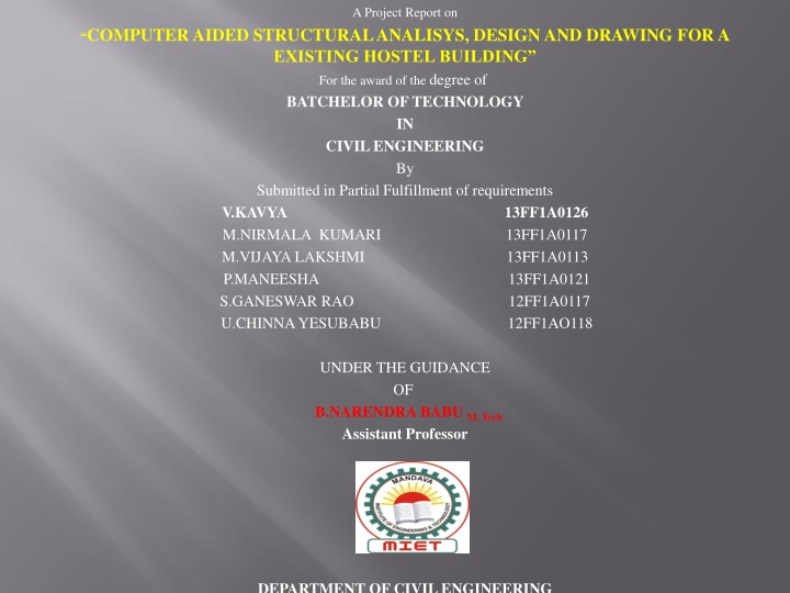
A Project Report on COMPUTER AIDED STRUCTURAL ANALISYS, DESIGN AND DRAWING FOR A EXISTING HOSTEL BUILDING For the award of the degree of BATCHELOR OF TECHNOLOGY IN CIVIL ENGINEERING By Submitted in Partial Fulfillment of requirements V.KAVYA M.NIRMALA KUMARI M.VIJAYA LAKSHMI P.MANEESHA S.GANESWAR RAO U.CHINNA YESUBABU 12FF1AO118 13FF1A0126 13FF1A0117 13FF1A0113 13FF1A0121 12FF1A0117 UNDER THE GUIDANCE OF B.NARENDRA BABU M. Tech Assistant Professor DEPARTMENT OF CIVIL ENGINEERING
ANALYSIS AND DESIGN OF A (G + 6) EXISTING COLLEGE HOSTEL BUILDING USING STAAD PRO ABSTRACT In order to compete in the ever growing competent market it is very important for a structural engineer to save time. as a sequel to this an attempt is made to analyze and design a Multistoried building by using a software package STAAD PRO. For analyzing a multi storied building one has to consider all the possible loadings and see that the structure is safe against all possible loading conditions. There are several methods for analysis of different frames like kani s method, cantilever method, portal method, Matrix method. The present project deals with the analysis of a multi storyed residential building of G+5 consisting of 5 apartments in each floor. The dead load &live loads are applied and the design for beams, columns, footing is obtained. STAAD Pro with its new features surpassed its predecessors, and compotators with its data sharing capabilities with other major software like AutoCAD, and MS Excel. We conclude that staad pro is a very powerful tool which can save much time and is very accurate in Designs. Thus it is concluded that staad pro package is suitable for the design of a multistoried building. The engineer has to keep in mind the municipal rules, regulations, and conditions , apply building bye laws with suitable environmental conditions to required financial capacity, water supply, sewage arrangement, provision of future, aeration, ventilation etc ., in suggestion of a particular type of plan to any client.
INTRODUCTION Building construction is the engineering deals with the construction of building such as residential houses. In a simple building can be define as an enclose space by walls with roof, food, cloth and the basic needs of human beings. In the early ancient times humans lived in caves, over trees or under trees, to protect themselves from wild animals, rain, sun, etc. as the times passed as humans being started living in huts made of timber branches. The shelters of those old have been developed nowadays into beautiful houses. Rich people live in sophisticated condition . Buildings are the important indicator of social progress of the county. Every human has desire to own comfortable homes on an average generally one spends his two- third life times in the houses. The security civic sense of the responsibility. These are the few reasons which are responsible that the person do utmost effort and spend hard earned saving in owning houses. A building frame consists of number of bays and storey. A multi-storey, multi- paneled frame is a complicated statically intermediate structure. A design of R.C building of G+6 storey frame work is taken up.
Statement of project Salient features: Utility of building : residential complex No of stories : G+4 Shape of the building : 12 APARTMENTS No of staircases : 3 No. of rooms: 40 Type of construction : R.C.C framed structure Types of walls : brick wall Geometric details: Ground floor : 3m Floor to floor height : 3m. Height of plinth : 0.6m Depth of foundation: 500mm Materials: Concrete grade : M30 All steel grades: Fe415 grade Bearing capacity of soil: 300KN/M2
LOADCASE DETAILS The following load cases are to be considered for residential buildings as follow Dead load Live load Wind load Seismic load Dead Loads: Dead loads consist of the permanent construction material loads compressing the roof, floor, wall, and foundation systems, including claddings, finishes and fixed equipment. Dead load is the total load of all of the components of the components of the building that generally do not change over time, such as the steel columns, concrete floors, bricks, roofing material etc. In staad pro assignment of dead load is automatically done by giving the property of the member. Dead load s are calculated as per IS 875 part 1 Live Loads: Live loads are produced by the use and occupancy of a building. Loads include those from human occupants, furnishings, no fixed equipment, storage, and construction and maintenance activities. As required to adequately define the loading condition, loads are presented in terms of uniform area loads, concentrated loads, and uniform line loads. Live loads are calculated as per IS 875 part 2 Wind loads: For wind calculations the following parameters are to be considered Basic wind speed Risk coffecient Terrain height and structure size factor Topography factor -
It can be mathematically expressed as follows: Vs.=Vb* K1* K2* K3 Where Vz= design wind speed at any height Z in m/s K1= probability factor (risk coefficient) K2=terrain height and structure size factor and K3=topography factor Design wind pressure=0.6Vz Wind loads are calculated as per IS 875 part 3 2 Seismic loads: For seismic load calculations the following parameters are to be considered Zone Factor Importance Factor Response Reduction Factor Time Period Average Response Acceleration Coeffecient Seismic weight depends upon the total mass of the structure by means of dead load and live load Seismic weight (Wi) = DL+ 50%LL (if LL>3) (Wi) = DL+ 25%LL (if LL>3) Seismic loads are calculated as per IS 1893:2002
This project is mostly based on software and it is essential to know the details about these software s. List of software s used 1. Staad pro(v8i) 2. Staad foundations 5(v8i) 3. Auto cad STAAAD pro STAAD
DESIGN OF BEAM Beams transfer load from slabs to columns .beams are designed for bending. In general we have two types of beam: single and double. Similar to columns geometry and perimeters of the beams are assigned. Design beam command is assigned and analysis is carried out, now reinforcement details are taken. Beam design: A reinforced concrete beam should be able to resist tensile, compressive and shear stress induced in it by loads on the beam. There are three types of reinforced concrete beams Single reinforced beams Double reinforced concrete Flanged beams DESIGN OF COLUMNS A column or strut is a compression member, which is used primary to support axial compressive loads and with a height of at least three it is least lateral dimension. A reinforced concrete column is said to be subjected to axially loaded when line of the resultant thrust of loads supported by column is coincident with the line of C.G 0f the column I the longitudinal direction. Depending upon the architectural requirements and loads to be supported , R. C columns may be cast in various shapes i.e square ,rectangle, and hexagonal , octagonal, circular. Columns of L shaped or T shaped are also sometimes used in multistoried buildings. DESIGN OF SLABS Slabs are plane structure member whose thickness is small as compare to its length and breadth. Slabs are most frequently used as roof coverage and floors in various shapes such as square, rectangle, circular, triangle, etc. in buildings Slabs supports mainly transverse loads and transfers them to supports (Beams and Walls) by bending action in one or more direction. 6.2 TYPES OF SLABS: Depending upon the ratio of longer span to shorter span (lx/ly) the slabs are classified as : One-way slab Two -way slab
3D VIEW OF BUILDING DEFLECTION DIAGRAM
B E A M N O. 196 D E S I G N R E S U L T S M20 Fe415 (Main) Fe415 (Sec.) LENGTH: 3790.0 mm SIZE: 230.0 mm X 300.0 mm COVER: 25.0 mm SUMMARY OF REINF. AREA (Sq.mm) ---------------------------------------------------------------------------- SECTION 0.0 mm 947.5 mm 1895.0 mm 2842.5 mm 3790.0 mm ---------------------------------------------------------------------------- TOP 909.75 126.72 124.84 0.00 564.23 REINF. (Sq. mm) (Sq. mm) (Sq. mm) (Sq. mm) (Sq. mm) BOTTOM 336.40 161.33 689.62 339.41 126.72 REINF. (Sq. mm) (Sq. mm) (Sq. mm) (Sq. mm) (Sq. mm) ---------------------------------------------------------------------------- SUMMARY OF PROVIDED REINF. AREA ---------------------------------------------------------------------------- SECTION 0.0 mm 947.5 mm 1895.0 mm 2842.5 mm 3790.0 mm ---------------------------------------------------------------------------- TOP 3-20 2-20 2-20 2-20 2-20 REINF. 1 layer(s) 1 layer(s) 1 layer(s) 1 layer(s) 1 layer(s) BOTTOM 3-12 2-12 7-12 4-12 2-12 REINF. 1 layer(s) 1 layer(s) 2 layer(s) 1 layer(s) 1 layer(s) SHEAR 2 legged 8 2 legged 8 2 legged 8 2 legged 8 2 legged 8 REINF. @ 110 mm c/c @ 110 mm c/c @ 110 mm c/c @ 110 mm c/c @ 110 mm c/c

 EXISTING COLLEGE HOSTEL")