Diode Circuits and Rectifiers: Applications and Operation
Explore the world of diode circuits and rectifiers, including full-wave and half-wave rectifiers, center-tapped full-wave rectifiers, bridge full-wave rectifiers, diode limiters, and more. Understand how these components function and their applications in electronics. Dive into examples and calculations to enhance your knowledge in analogue electronics.

Download Presentation

Please find below an Image/Link to download the presentation.
The content on the website is provided AS IS for your information and personal use only. It may not be sold, licensed, or shared on other websites without obtaining consent from the author.If you encounter any issues during the download, it is possible that the publisher has removed the file from their server.
You are allowed to download the files provided on this website for personal or commercial use, subject to the condition that they are used lawfully. All files are the property of their respective owners.
The content on the website is provided AS IS for your information and personal use only. It may not be sold, licensed, or shared on other websites without obtaining consent from the author.
E N D
Presentation Transcript
Chapter Two Diode and its Application Lecture 5 2
Full wave rectifiers Although half-wave rectifiers have some applications, the full-wave rectifier is the most commonly used type in DC power supplies. A full-wave rectifier allows unidirectional (one-way) current through the load during the entire of the input cycle. Whereas a half-wave rectifier allows current through the load only during one-half of the cycle. The output voltage have twice the input frequency. VAVG = 2VP/ = VAVG is approximately 63.7 % of Vp Figure 14 3
Center-Tapped Full-Wave Rectifier Operation A center-tapped rectifier uses two diodes connected to the secondary of a center-tapped transformer, as shown in Figure 1. Figure 1: Basic operation of a center-tapped full-wave rectifier. 4
The Bridge Full-wave rectifiers The Bridge Full-Wave rectifier uses four diodes connected across the entire secondary, as shown in Figure below. 5
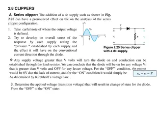
Diode Limiters Diode circuits, called limiters or clippers, are used to clip off portions of signal voltages above or below certain levels. Point A is limited to +0.7V when the input voltage exceeds this value (Figure 3(a)). If the diode is turned around, as in Figure 3(b), the negative part of the input voltage is clipped off. When the diode is forward-biased during the negative part of the input voltage, point A is held at -0.7V by the diode drop. Figure 3: Examples of diode limiters (clippers). 6
A power supply or voltage divider can attain the desired amount of limitation. The amount clipped can be adjusted with different levels of VBIAS. The peak output voltage across RL is determined by the following equation: ?? ????= ??? ?1+ ?? 7
Example 2: What would you expect to see displayed on an oscilloscope connected across RL in the limiter shown in the following Figure/ Solution: The diode is forward-biased and conducts when the input voltage goes below -0.7V. So, for the negative limiter, determine the peak output voltage across RL by. ?? ?1+ ?? 110k The scope will display an output waveform as shown in following Figure 100k = ???= 10V = 9.09V 8
Diode Clampers Another type of diode circuit, called a clamper, is used to add or restore a dc level to an electrical signal. The capacitor charges to the peak of the supply minus the diode drop. Once charged the capacitor acts like a battery in series with the input voltage. The AC voltage will ride along with the DC voltage. The polarity arrangement of the diode determines whether the DC voltage is negative or positive. 9
Voltage Multiplier Voltage multipliers use clamping action to increase peak rectified voltages without the necessity of increasing the transformer s voltage rating. Multiplication factors of two, three, and four are common. Voltage multipliers are used in high-voltage, low-current applications such as cathode-ray tubes (CRTs) and particle accelerators. In the Figure below, a half-wave voltage doubler, voltage doubler is a voltage multiplier with a multiplication factor of two. Once C1 and C2 charge to the peak voltage, it acts like two batteries in series, effectively doubling the voltage output. The current capacity for voltage multipliers is low. 10
The full-wave voltage doubler arrangement of diodes and capacitors takes advantage of positive and negative peaks to charge the capacitors, giving them more current capacity. Voltage triplers and quadruplers utilize three and four-diode-capacitor arrangements, respectively. 11
Typical diode packages with terminal identification. The letter K is used for cathode to avoid confusion with certain electrical quantities that are represented by C. Case type numbers are indicated for each diode. 12