Electrical Engineering Basics: Series Circuits and Potentials
Explore the fundamentals of series circuits and potential dividers in electrical engineering. Understand voltage distribution, current flow, and circuit analysis. Enhance your knowledge with in-depth examples and solutions provided in the course materials. Unlock the principles behind mechatronics and industrial robotics under the guidance of Prof. Dr. Abou-Hashema Mustafa El-Sayed.

Download Presentation

Please find below an Image/Link to download the presentation.
The content on the website is provided AS IS for your information and personal use only. It may not be sold, licensed, or shared on other websites without obtaining consent from the author. If you encounter any issues during the download, it is possible that the publisher has removed the file from their server.
You are allowed to download the files provided on this website for personal or commercial use, subject to the condition that they are used lawfully. All files are the property of their respective owners.
The content on the website is provided AS IS for your information and personal use only. It may not be sold, licensed, or shared on other websites without obtaining consent from the author.
E N D
Presentation Transcript
SERIES CIRCUITS COURSE: ELECTRICAL ENGINEERING COURSE CODE: ELE 115 LECTURE NO: #1 PROGRAM: MECHATRONICS AND INDUSTRIAL ROBOTICS SUPERVISOR: PROF.DR. ABOU-HASHEMA MUSTAFA EL-SAYED
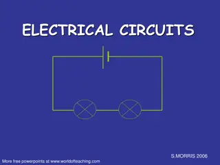
SERIES CIRCUITS Figure 5.1 shows three resistors R1, R2 and R3 connected end to end, i.e. in series, with a battery source of V volts. Since the circuit is closed a current, I will flow and the p.d. across each resistor may be determined from the voltmeter readings V1, V2 and V3
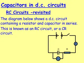
POTENTIAL DIVIDER The voltage distribution for the circuit shown in Figure 5.5(a) is given by:
The circuit shown in Figure 5.5(b) is often referred to as a potential divider circuit. Such a circuit can consist of a number of similar elements in series connected across a voltage source, voltages being taken from connections between the elements. Frequently the divider consists of two resistors as shown in Figure 5.5(b), where A potential divider is the simplest way of producing a source of lower e.m.f. from a source of higher e.m.f., and is the basic operating mechanism of the potentiometer, a measuring device for accurately measuring potential Differences.
EXAMPLES: Good luck Good luck


 is often referred to")