Feedback in Amplifier Circuits: Gain Trade-offs and Distortion Reduction

The trade-off of gain for improved input and output resistance in amplifier circuits along with the reduction in frequency distortion and the effect of negative feedback on gain and bandwidth. Practical feedback circuits and voltage-series feedback connections are also discussed.

Download Presentation

Please find below an Image/Link to download the presentation.
The content on the website is provided AS IS for your information and personal use only. It may not be sold, licensed, or shared on other websites without obtaining consent from the author.If you encounter any issues during the download, it is possible that the publisher has removed the file from their server.
You are allowed to download the files provided on this website for personal or commercial use, subject to the condition that they are used lawfully. All files are the property of their respective owners.
The content on the website is provided AS IS for your information and personal use only. It may not be sold, licensed, or shared on other websites without obtaining consent from the author.
E N D
Presentation Transcript
Example 18.1 demonstrates the trade-off of gain for improved input and output resistance. Reducing the gain by a factor of 11 (from 100 to 9.09) is complemented by a reduced output resistance and increased input resistance by the same factor of 11. Reducing the gain by a factor of 51 provides a gain of only 2 but with input resistance feedback connection. increased by the factor of 51 (to over 500 k) and output resistance reduced from 20 kto under 400 . Feedback offers the designer the choice of trading away some of the available amplifier gain for other improved circuit features
Reduction in Frequency Distortion For a negative-feedback amplifier having ?A>>1, the gain with feedback is Af 1/?. It follows from this that if the feedback network is purely resistive, the gain with feedback is not dependent on frequency even though the basic amplifier gain is frequency dependent. Practically, the frequency distortion arising because of varying amplifier gain with frequency is considerably reduced in a negative- voltage feedback amplifier circuit.
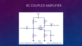
Voltage Voltage- -Series Feedback Series Feedback Fig.18.7 shows an FET amplifier stage with voltage-series feedback. A part of the output signal (Vo) is obtained using a feedback network of resistors R1 and R2. The feedback voltage Vf is connected in series with the source signal Vs, their difference being the input signal Vi. Without feedback the amplifier gain is: Where RL is the parallel combination of resistors:
Using the values of A and above in Equation Af isthe gain with negative feedback
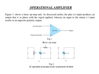
Fig.18.8 shows a voltage-series feedback connection using an op-amp. The gain of the op-amp, A, without feedback, is reduced by the feedback factor
Fig.18.9 provides voltage-series feedback. The signal voltage, Vs, is the input voltage, Vi. The output voltage, Vo, is also the feedback voltage in series with the input voltage. The amplifier, as shown in Fig.18.9, provides the operation with feedback. The operation of the circuit without feedback provides Vf = 0, so that
Current-Series Feedback Another feedback technique is to sample the output current (Io) and return a proportional voltage in series with the input. While stabilizing the amplifier gain, the current- series feedback connection increases input resistance. Fig.18.10 shows a single transistor amplifier stage. Since the emitter of this stage has an unbypassed emitter, it effectively has current-series feedback. The current through resistor RE results in a feedback voltage that opposes the source signal applied so that the output voltage Vo is reduced. To remove the current-series feedback, the emitter resistor must be either removed or bypassed by a capacitor (as is usually done).
WITHOUT FEEDBACK WITH FEEDBACK
This is a transfer resistance gain. The more usual gain is the voltage gain with feedback, The circuit of Fig. 18.13 is a voltage-shunt feedback amplifier using an FET with
Calculate the voltage gain with and without feedback for the circuit of Fig. 18.13a